
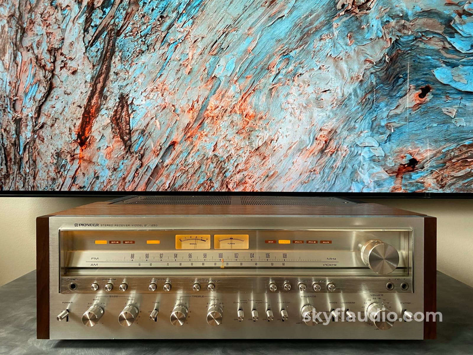

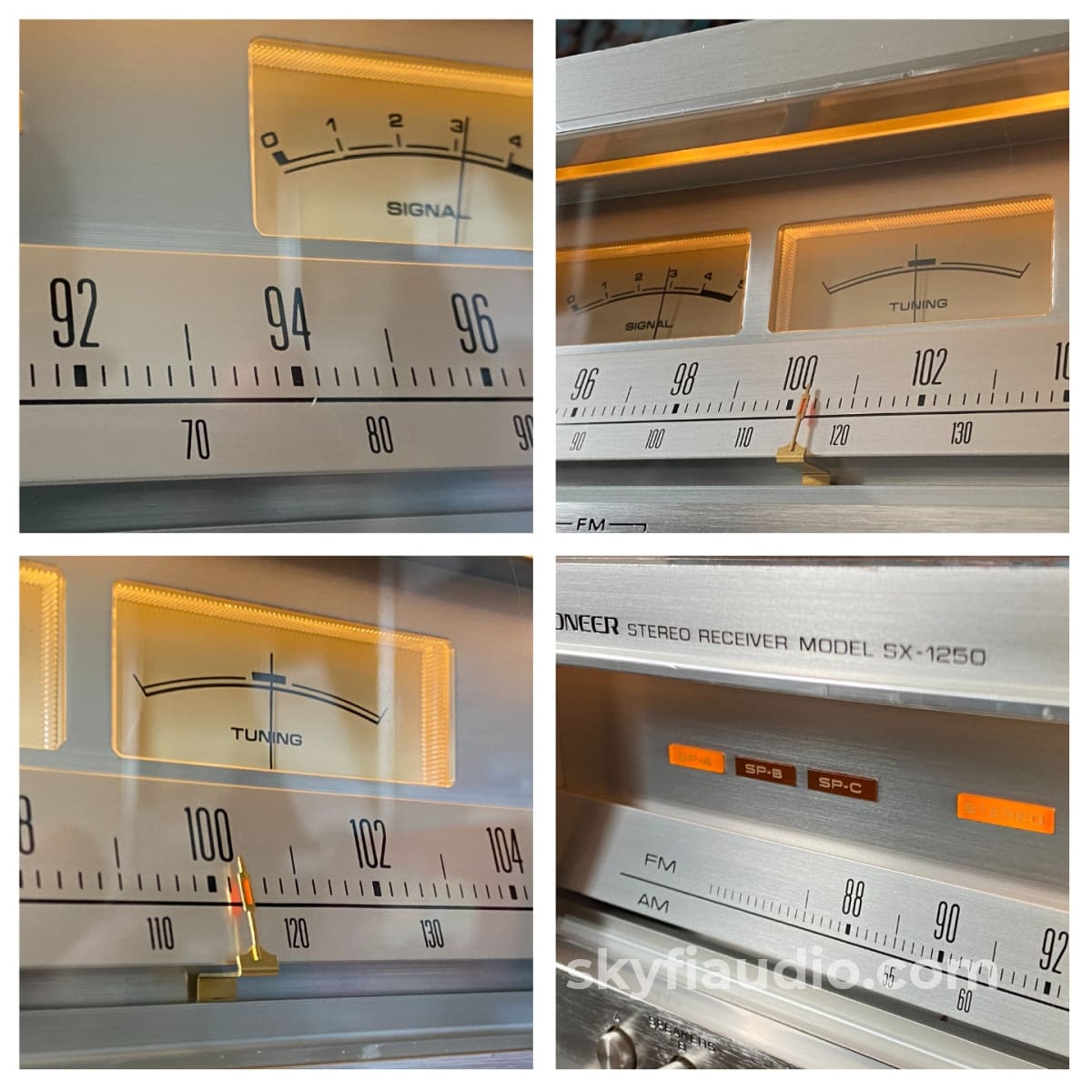
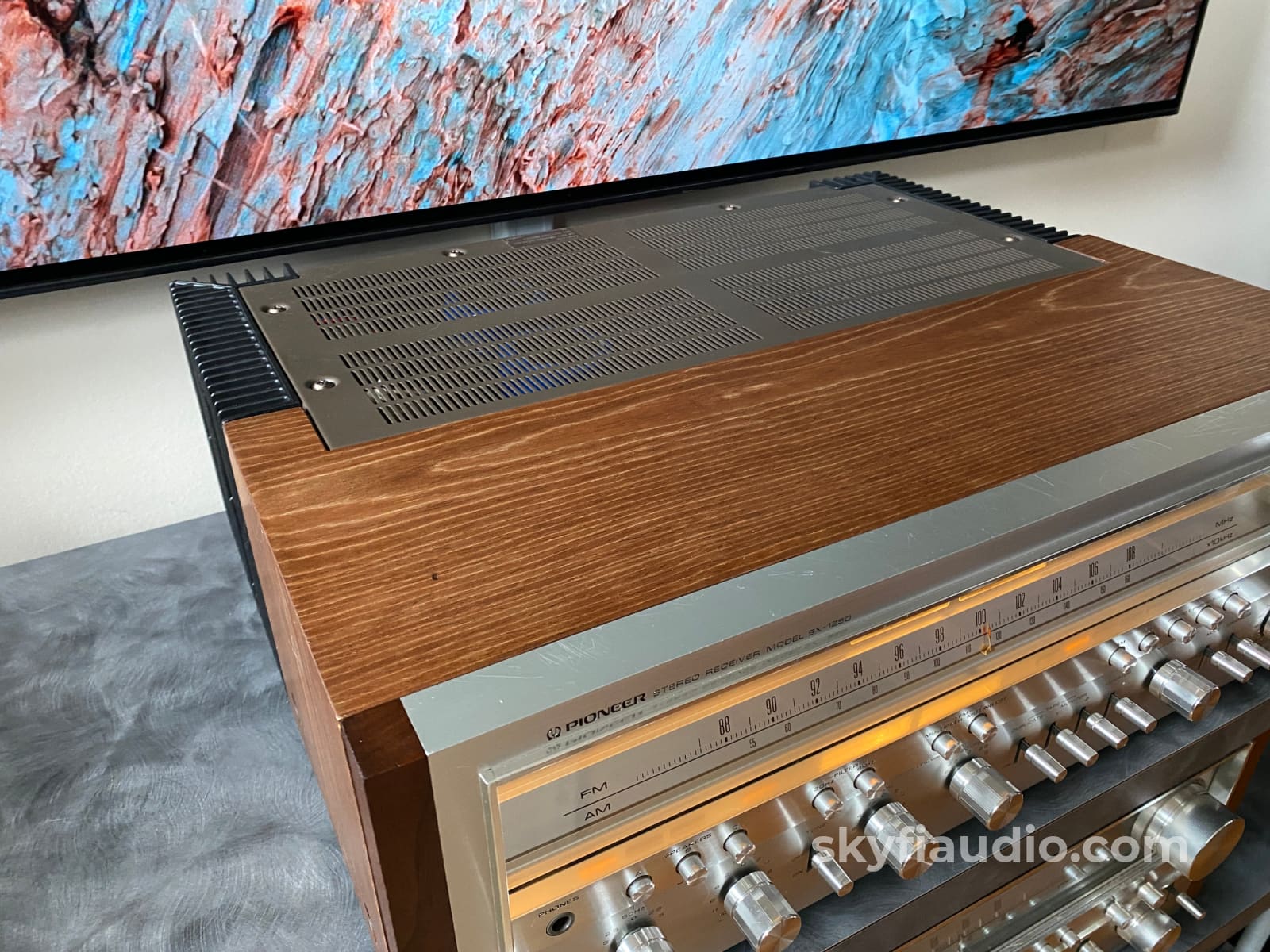
Pioneer SX-1250 Stereo Receiver - Fully Restored w/Rustic Walnut Veneer
Free Shipping (Contiguous U.S. Only)
Pickup currently unavailable at SkyFi 479
Pioneer SX-1250 Stereo Receiver - Fully Restored w/Rustic Walnut Veneer
SkyFi 479
479 South Broad Street
Glen Rock NJ 07452
United States
General:
The Pioneer SX-1250 is considered by many to be the best receiver that Pioneer ever produced.
Its build quality, output power, and classic aesthetics place it among the must have receivers from the power wars era.
The SX-1250 is rated at 160W per channel into 8 ohms with less than 0.1% THD at any output power or frequency. Post restoration, these units consistently test below 0.05% THD at 1KHz with a max clipping power approaching 180W per channel with both channels driven simultaneously.
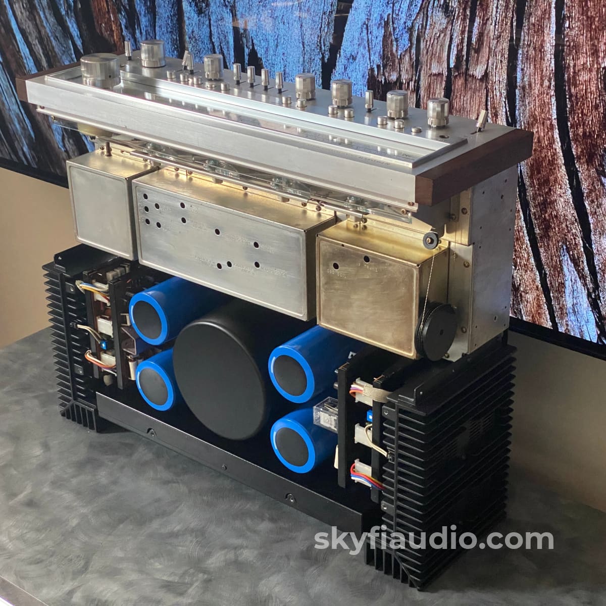
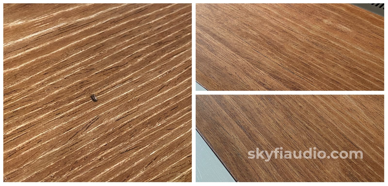
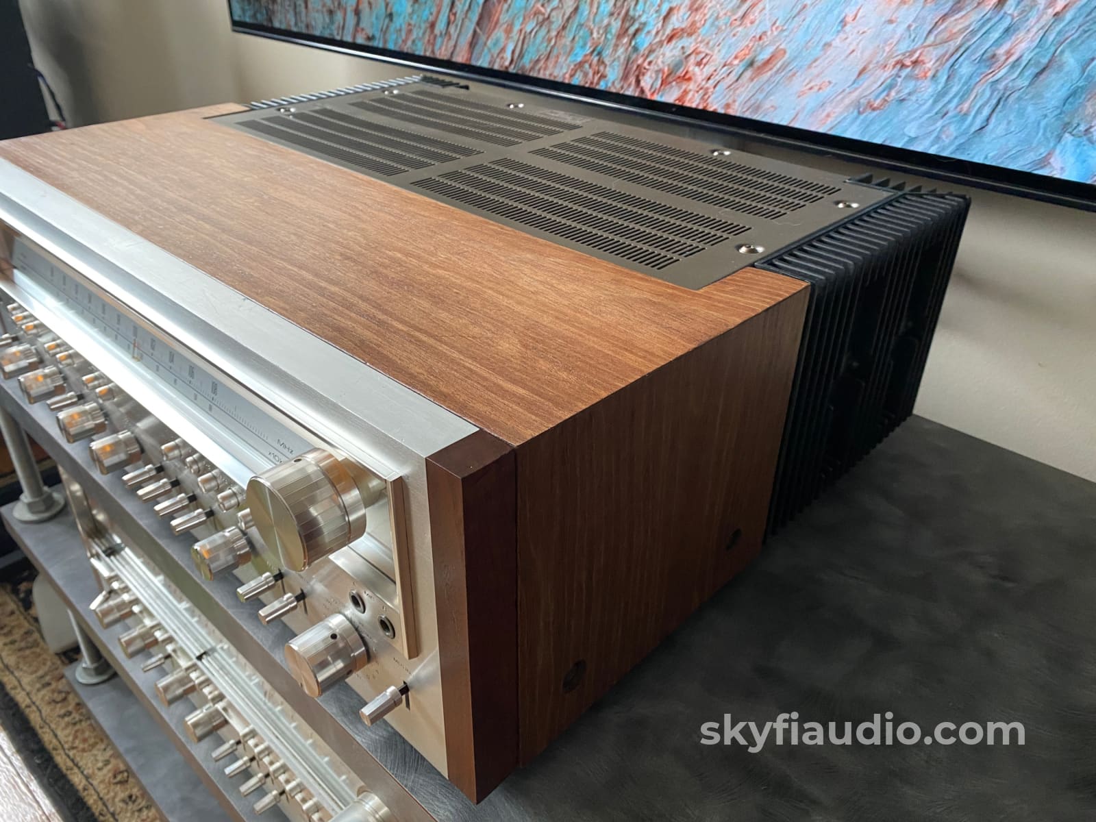
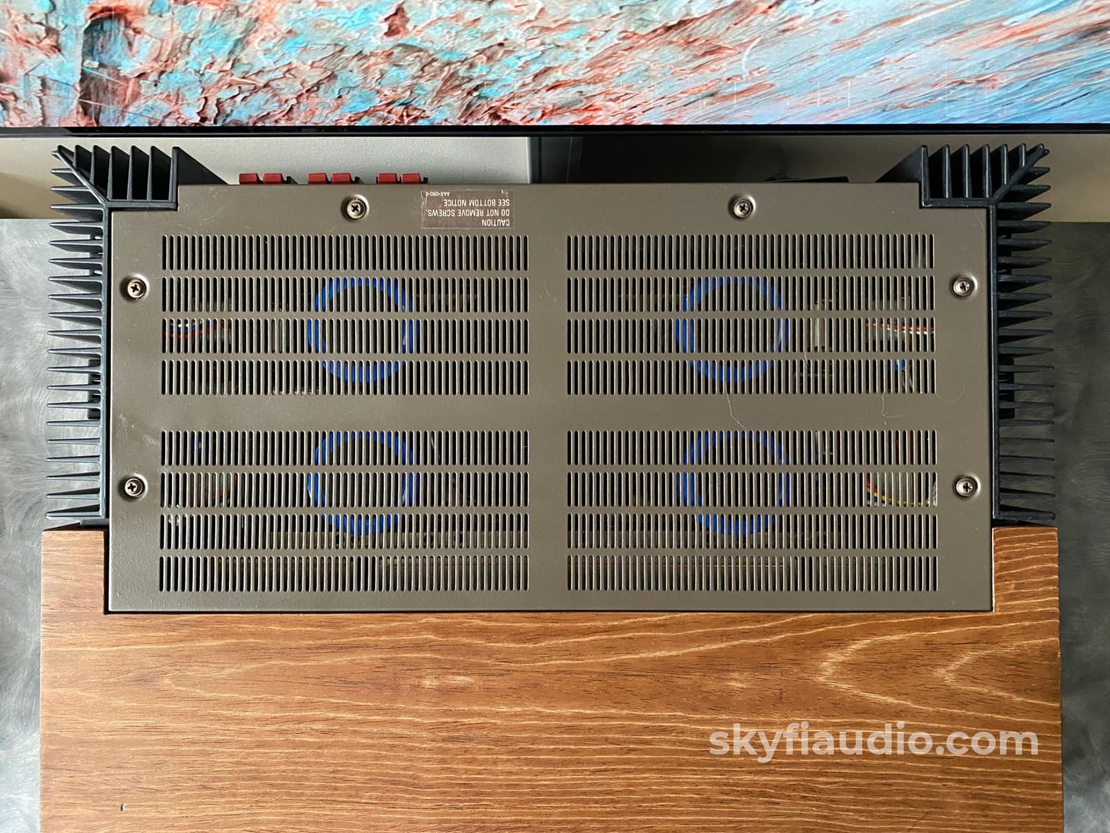
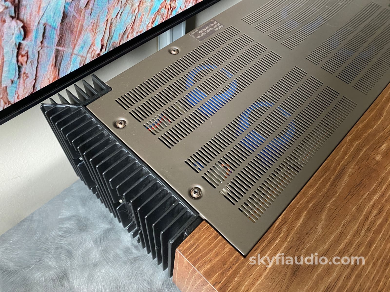
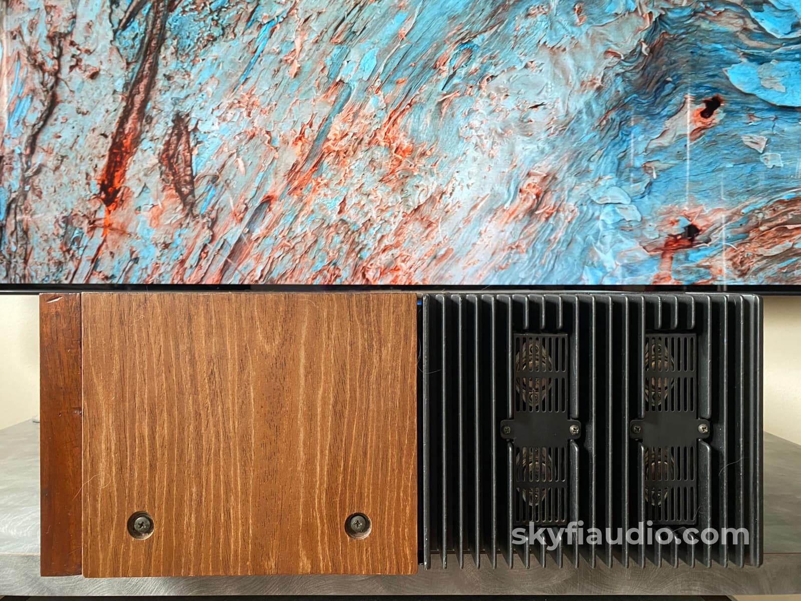
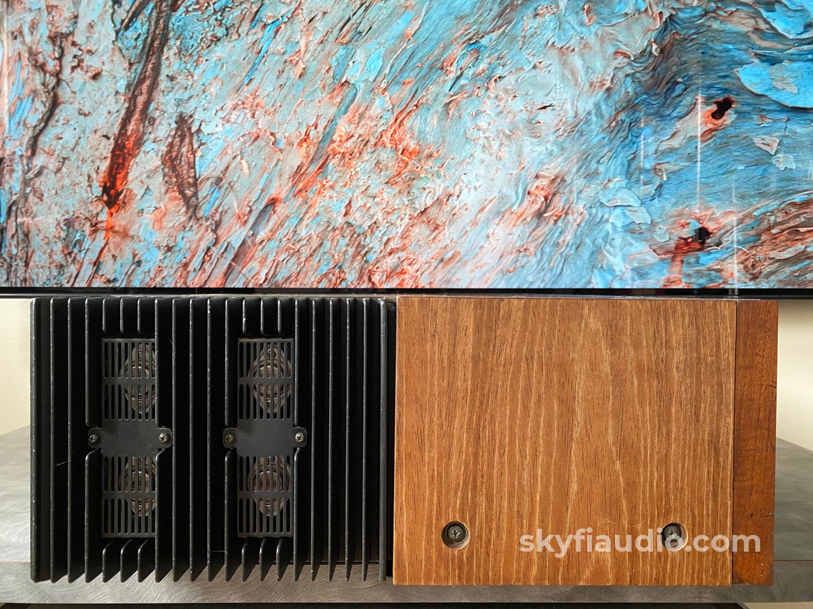
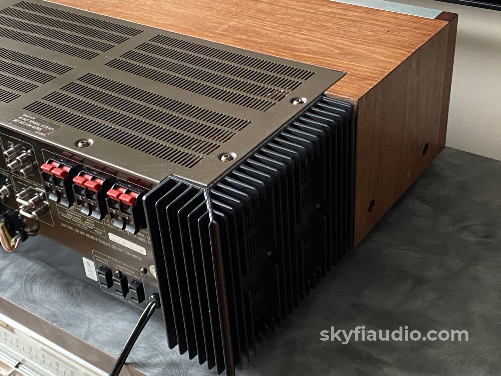
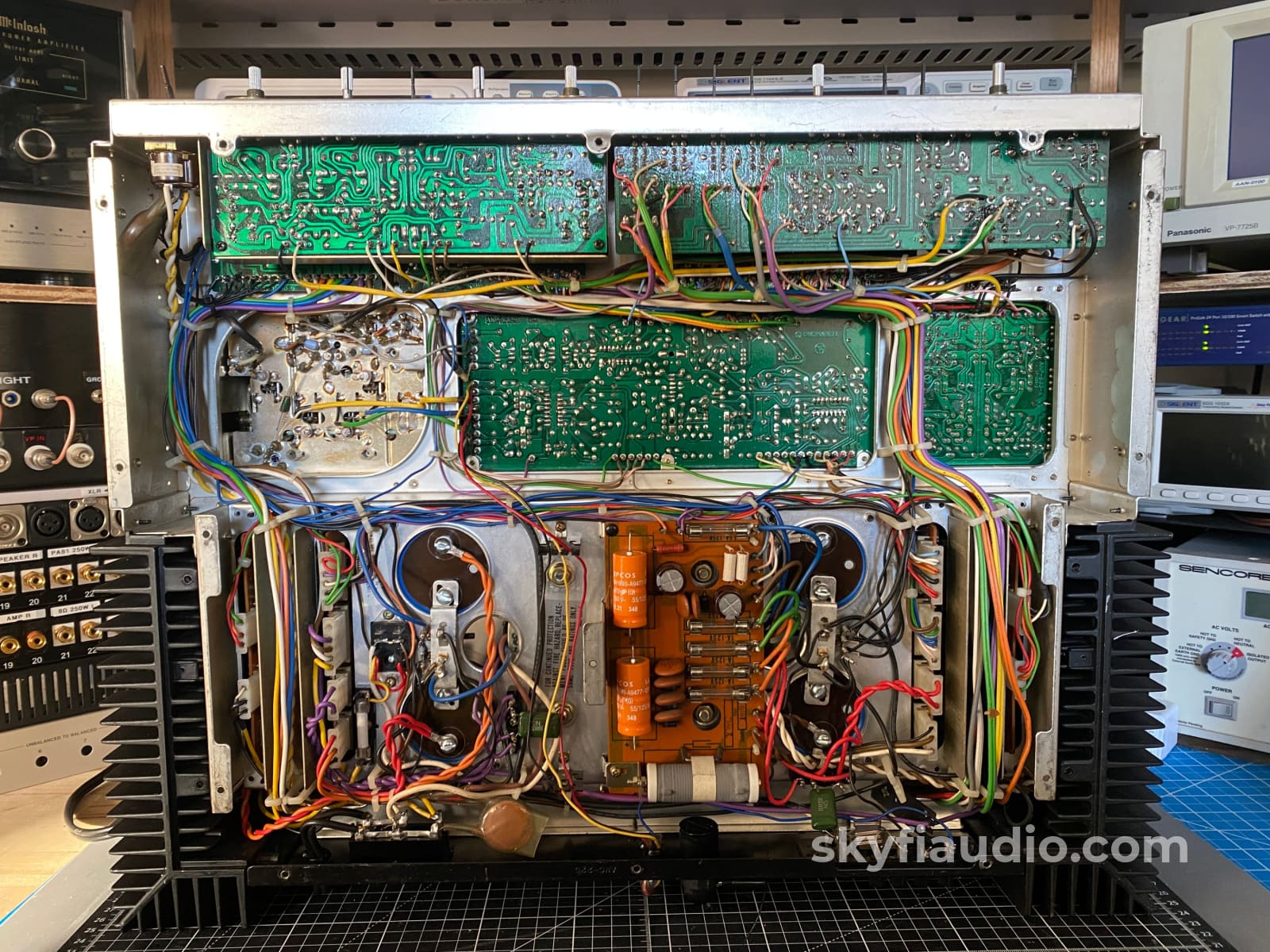
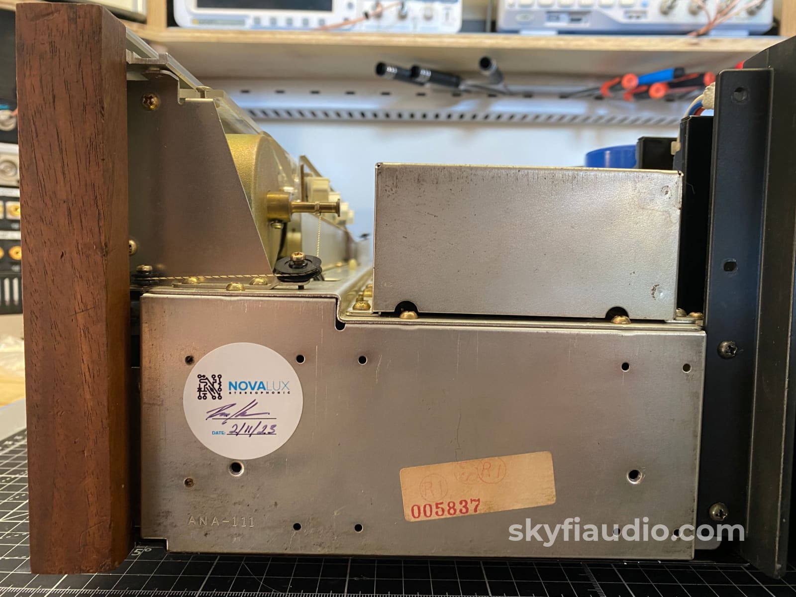
This specific example underwent a full cosmetic and electronic restoration by our lead restoration technician Ben at Novalux Stereophonic. The cosmetic work included removal and repainting of the heat sinks and top metal cover, along with a fresh walnut veneer on the cabinet featuring a rustic finish.
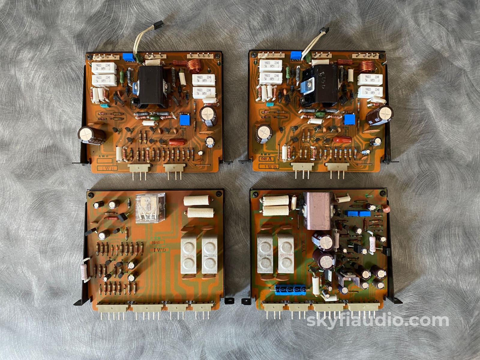
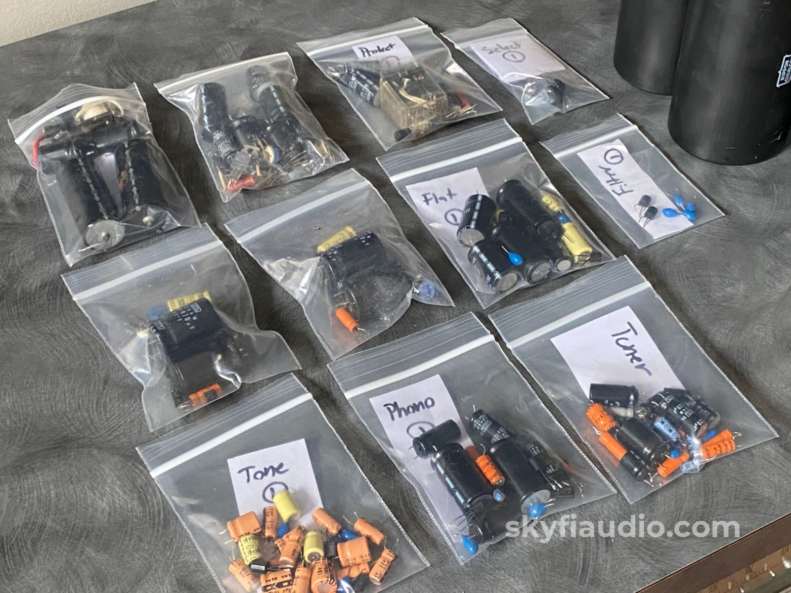
Electronically, this unit received a full overhaul.
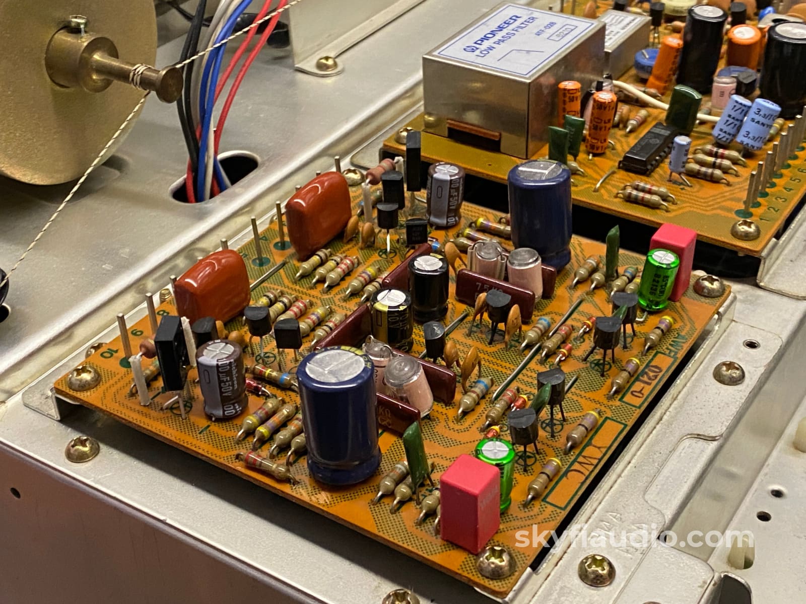
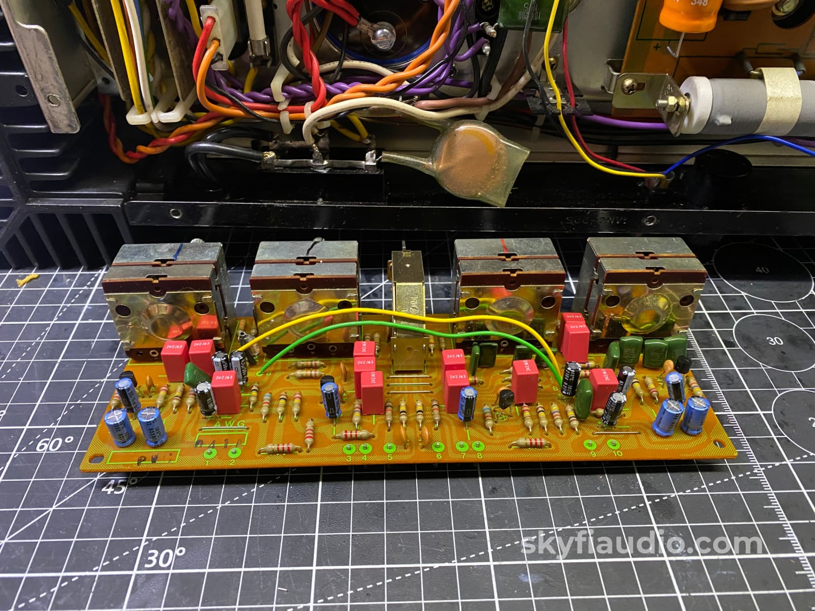
Every electrolytic capacitor in the unit was replaced including the large 22000uF main filter capacitors. All known failure points have been addressed. The power supply board which suffers from extended heat stress has received all new silicon to make it stable for the long haul. Relays replaced, indicator lamps converted to LED, all controls cleaned, and AM/FM tuner aligned.
A full restoration report can be made available upon request.
Then an extensive post-restoration battery of bench and listening tests were preformed to ensure stable operation.
THD+N Test Results at rated power (160W) - Aux Input, Volume 50% - Panasonic VP-7725
- 160W 1KHz 0.0219% / 0.0143%
- 160W 20KHZ 0.0668% / 0.0401%
- 160W 20Hz 0.0209% / 0.0137%
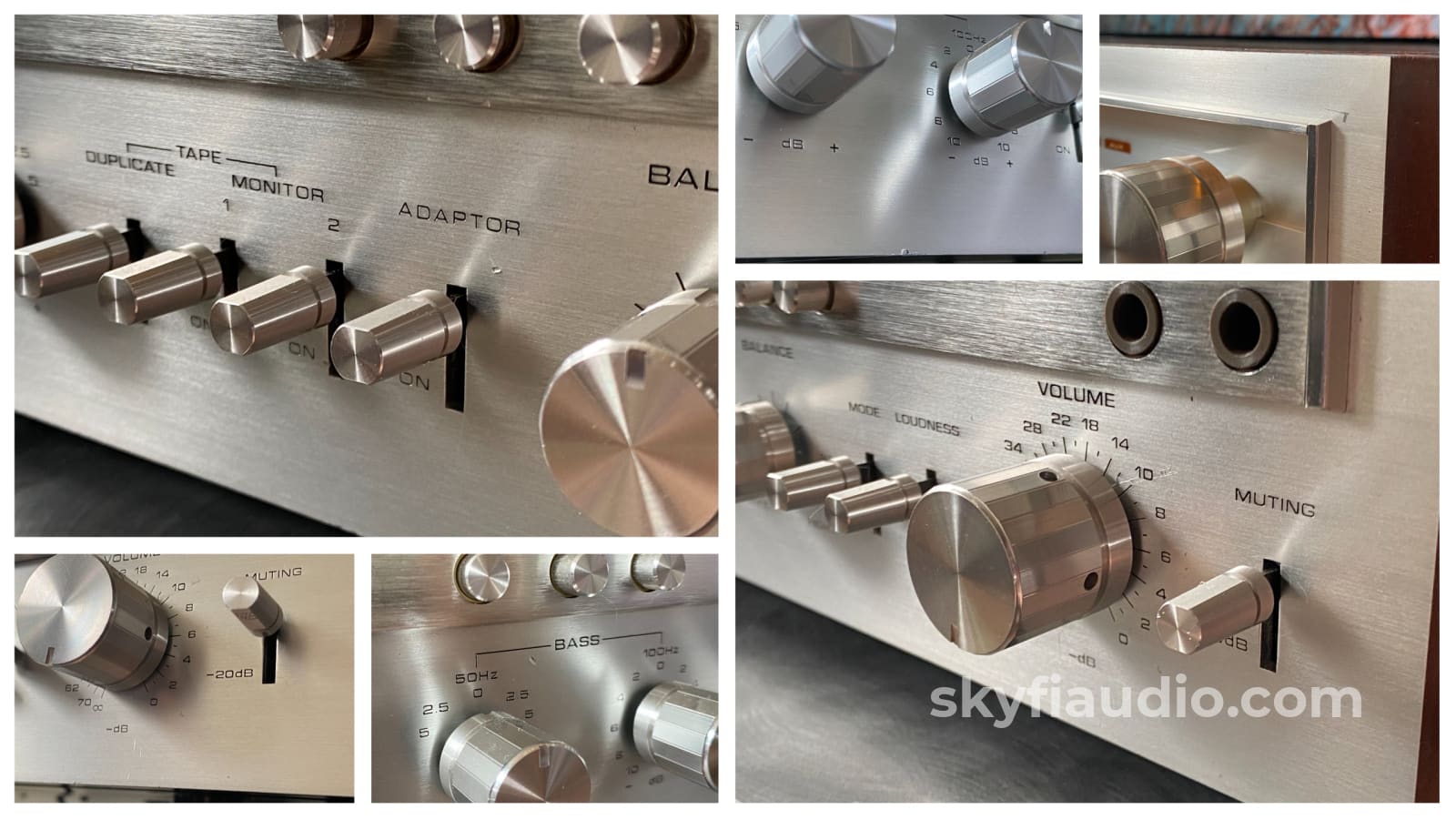
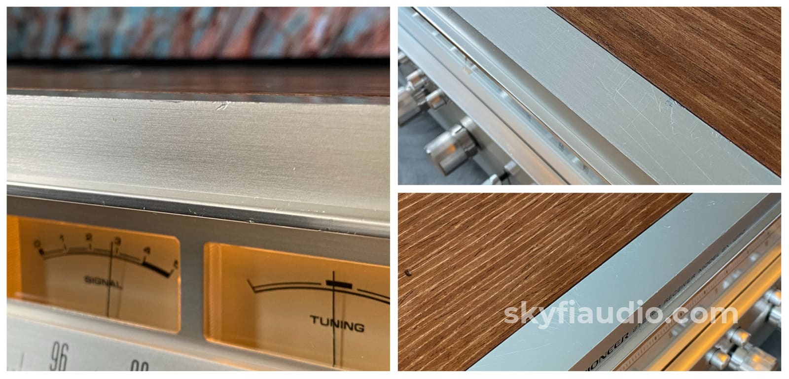
Cosmetic Notes
• This example has light cosmetic blemishes to the faceplate, knobs, and other metal surfaces. (See Images)
Brand Background:
Link to Pioneer Home Audio History
https://global.pioneer/en/corp/info/history/chronology/archives/1968
Ownership:
Multiple Owners
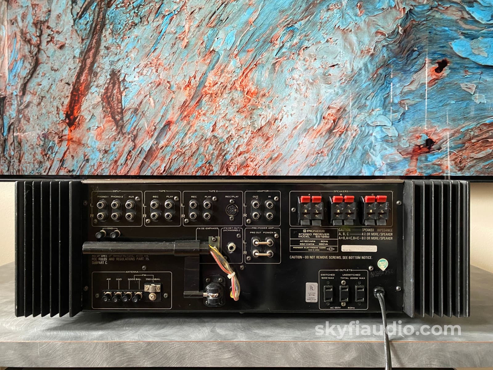
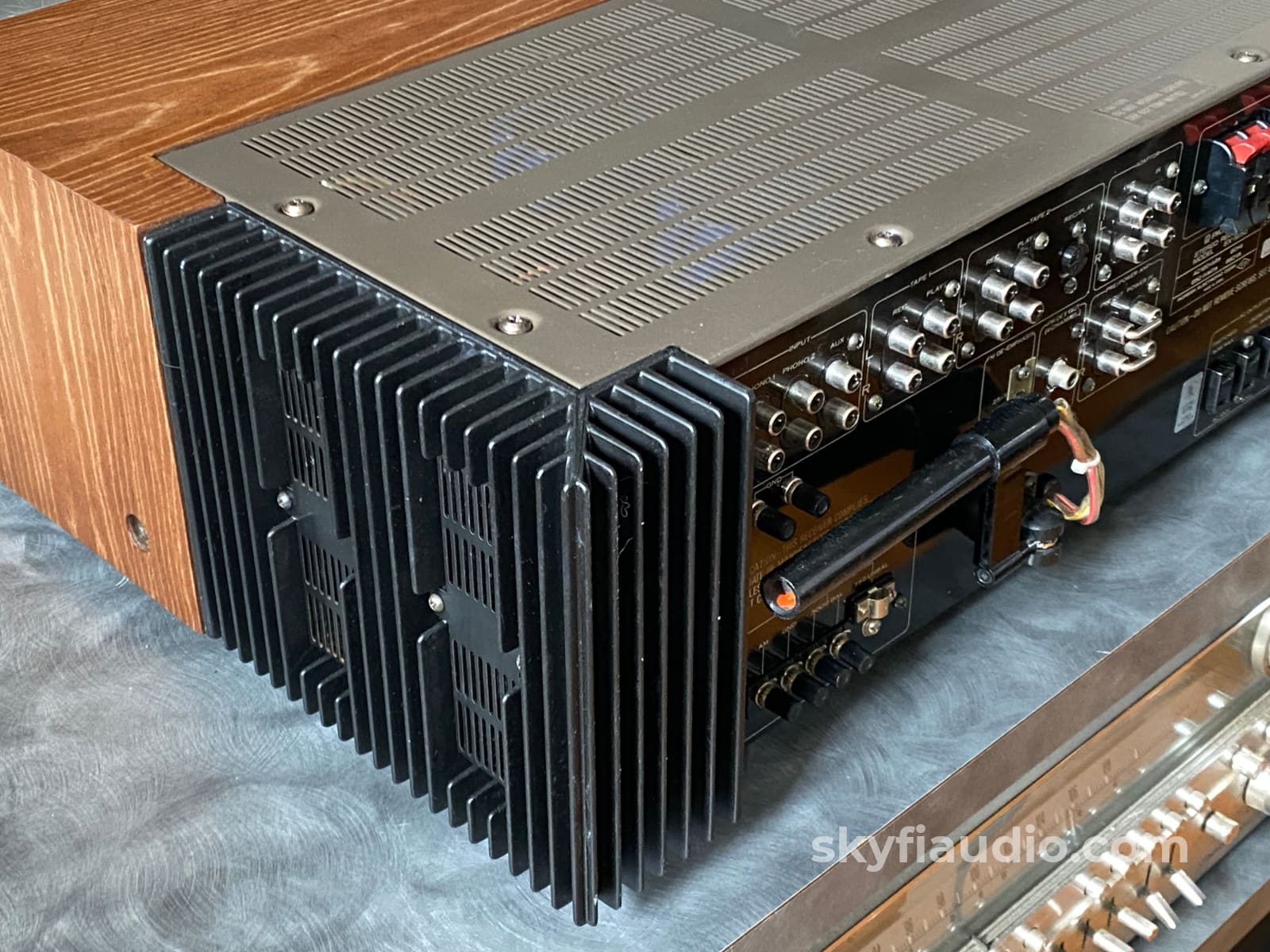
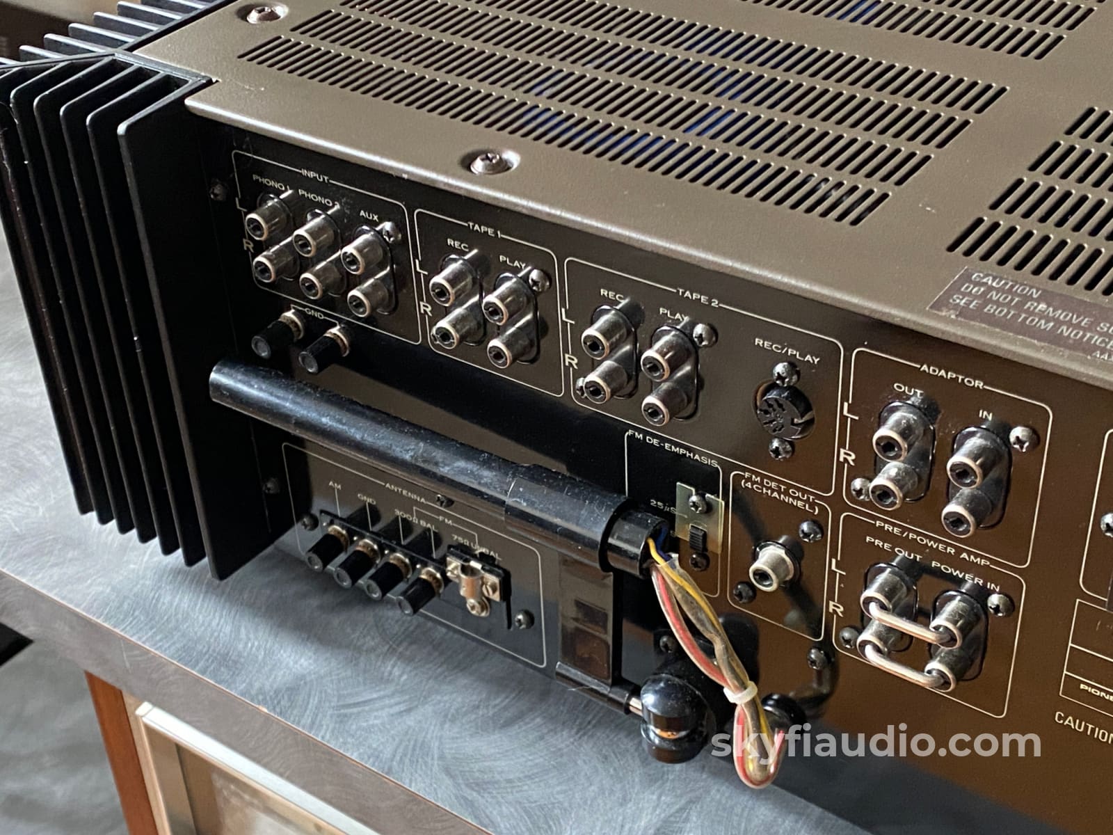
Connections:
RCA Jacks on all inputs and outputs. Bare wire or pin spring terminal outputs for speakers. Screw in connectors for antennas. Switch and unswitched AC outlets.
General Sound:
Powerful and clean, accurate with minimal coloration.
Cosmetic Condition:
6 - Moderate Signs of Wear
https://skyfiaudio.com/pages/our-rating-scale
Working Condition:
Working perfectly and tested in our lab.
Included:
As pictured
Packing:
Will be packed using our highly developed in-house process and custom packing materials.Dimensions:
22" x 7.5" x 18.75"
Weight:
65 lbs.
Approximate Age:
1976
Reviews:
https://thevintagehifishack.com/197677-pioneer-sx-1250/
Link to Manual:
Recommended Cables:
Kimber Kable - RCA Interconnects - Better
Kimber Kable - RCA Interconnects - Best
Kimber Kable - Speaker Cables - Better
Kimber Summit Series Monocle XL Speaker Cables (PAIR) - Best
Kimber Summit Series BiFocal XL Bi-Wire Speaker Cables (PAIR) - Best If Applicable
Testing Process:
The SkyFi Testing Process for Preamplifiers:
We start with a visual inspection of all internal components to make sure that there are no signs of heat stress or damage. Capacitors are checked for telltale signs of predictive failure including bulging, shrunken wrappers, or physical leakage. We also inspect the PCB’s for discoloration from resistors or transistors that may have been running hot. On vintage units we often spot check select capacitors for value and ESR.
When we first power on a preamplifier we connect its RCA output to a Sencore PA81 Power Analyzer which simulates real world loading conditions and gives us an oscilloscope interface. The first order of business is checking that the volume control works smoothly throughout its entire range with acceptable channel balance. This is accomplished by feeding a 1KHz sine wave into one of the preamp’s line level inputs while monitoring the preamp’s output on an oscilloscope. We then switch to a 1KHz square wave to test the tone controls, loudness function, and filters where applicable. During this step we are watching for equal alteration of the test signal by both channels. This also helps us identify dirty controls that will need treatment. Once the basic line stage functions are verified, we test each input individually. This is especially important for devices that use relays to select their sources. If the preamp is equipped with a phono stage we test that as well. We use an inverse RIAA filter which allows us to feed a reference test signal into the phono input with the proper RIAA equalization and level. A square wave or sine sweep is used to verify that the device’s phono stage is faithfully reproducing the RIAA curve. If the preamp under test has balanced inputs and/or outputs these are tested as well.
We finish up our bench testing with a listening test with our bench amplifier and reference speakers. During this test we check for hum or hiss that may not have shown up in earlier testing. We also check that all of the tone controls and filters perform as expected. If the preamplifier has remote control functions these are also tested. Preamps with tube circuits or complicated power supply topologies are connected at our long term test rig for extended stress testing under real world conditions.
The SkyFi Testing Process for Solid State Amplifiers:
We start with a visual inspection of all internal components to make sure that there are no signs of heat stress or damage. Capacitors are checked for telltale signs of predictive failure including bulging, shrunken wrappers, or physical leakage. We also inspect the PCBs for discoloration from resistors or transistors that may have been running hot. On vintage units we often spot check select capacitors for value and ESR.
If the amplifier passes visual inspection, we move on to a controlled power on sequence using a Sencore safety analyzer to monitor current draw in real time. Once the amplifier is determined to be safe to operate, we connect it to full AC mains for function and power testing. We connect the speaker outputs of the amplifier to a Sencore PA81 Power Analyzer which acts as a dummy load, DC offset monitor, and oscilloscope interface. We start with a low level 1KHz test signal at the amplifier’s input and slowly increase its amplitude while monitoring the output on an oscilloscope for signs of noise, clipping, distortion, or improper channel balance. We continue increasing the signal level until the amplifier reaches clipping. At this point we take an output power measurement and compare it to the spec sheet of the amplifier to verify proper performance. If the device under test has both balanced and single ended inputs they are both tested at this time. We finish off the bench evaluation with a 1KHz square wave check and a 20Hz to 20KHz sine sweep to assess the amplifier’s frequency response characteristics. This battery of tests will usually reveal if the amplifier has any issues that need further attention.
Before the device leaves the bench, we perform a listening test with actual music using a variety of preferred test tracks. Our benches are outfitted with familiar monitor speakers which help us identify inconsistencies that will not always show up on our test gear. The main things that we are listening for are hum or noise with no signal present, proper center image, clicks, pops, or any other obvious undesirable audio characteristics.
If the unit passes all of these tests it is moved to our long term testing rig where we simulate real word operating conditions for 6-8 hours. This allows us to monitor the unit for signs of thermal runaway or intermittent issues that only crop up when the unit has fully come up to temperature.
The SkyFi Testing Process for Tuners:
We start with a visual inspection of all internal components to make sure that there are no signs of heat stress or damage. Capacitors are checked for telltale signs of predictive failure including bulging, shrunken wrappers, or physical leakage. We also inspect the PCBs for discoloration from resistors or transistors that may have been running hot. On vintage units we often spot check select capacitors for value and ESR. Vintage analog tuners also have moving parts related to the tuning gang and dial string. These parts are inspected for smooth operation.
If the unit passes visual inspection it is bench tested for a handful of key performance parameters using a Sencore SG80 AM/FM Stereo Analyzer. The SG80 allows us to “simulate” an ideal radio station using precision test signals instead of music. This device, in conjunction with an oscilloscope allows us to properly evaluate the following parameters:
1. AM Reception (Where Applicable)
2. FM Mono Reception & Tuning Meter Function
3. FM MPX Reception (Stereo)
4. Dial Tracking - How accurately the tuner dial or display indicates the actual frequency of the broadcast being received.
5. Stereo Separation - A properly working stereo tuner will have minimal crosstalk between the left and right channel.
6. Sensitivity & Signal Strength Meter Function - By lowering the output of the SG80 we can simulate weak stations and determine how well the tuner will be able to pull in weak distant stations. This adjustment also helps us verify signal strength meter function.
If the tuner has acceptable performance related to the parameters above we connect the unit for listening tests with a simple dipole antenna. We listen for audio reproduction quality of local stations and evaluate how many stations the tuner can receive while we sweep through the dial. We are looking to verify that the tuner can decode stereo on strong local broadcasts and pick up a wide variety of local stations at the bottom, middle, and top of the frequency band. At this point we also test convenience features such as muting, filters, built in oscilloscope function, etc.
We finish up with an extended listening test on our long term test rig. We tune in a strong local station and monitor for drift over a 2-3 hour period.
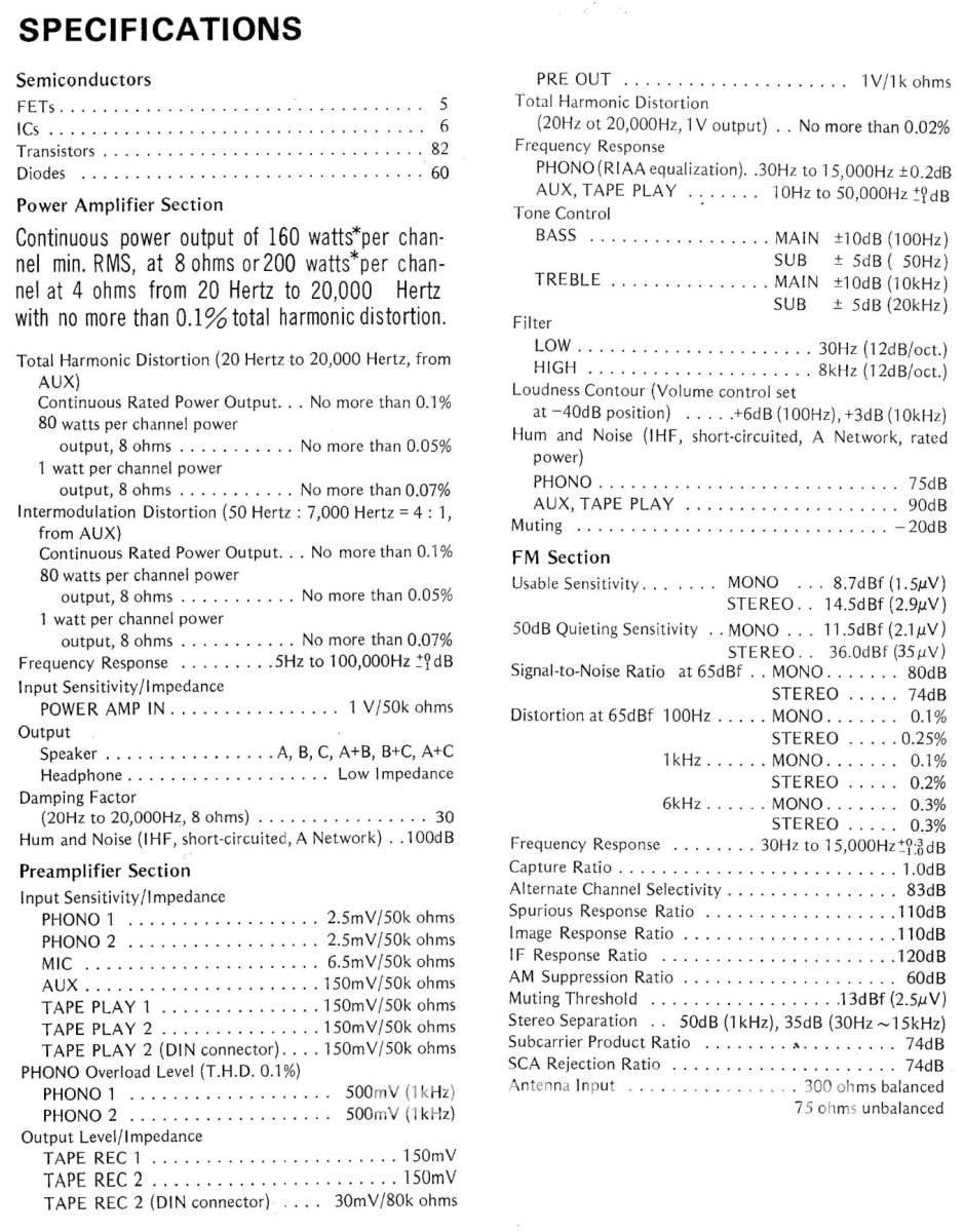
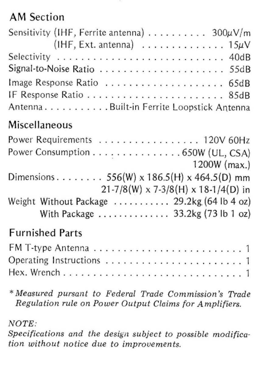
Specs:
Please see the linked manual above, or our last photos for full specifications
Power Output:
160 watts per channel RMS into 8 ohms
Harmonic Distortion:
Less than 0.1%
Intermodulation Distortion:
Less than 0.1%
FM Sensitivity:
1.5uV
FM Capture Ratio:
1.00
FM Harmonic Distortion Mono:
<0.1%
FM Harmonic Distortion Stereo:
<0.2%
Choose options