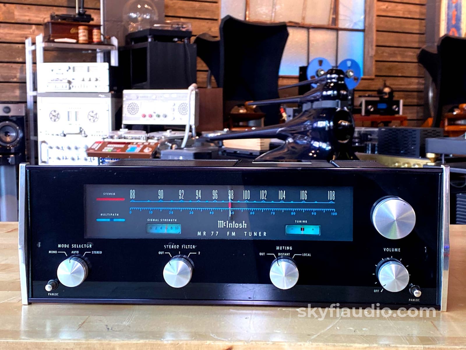
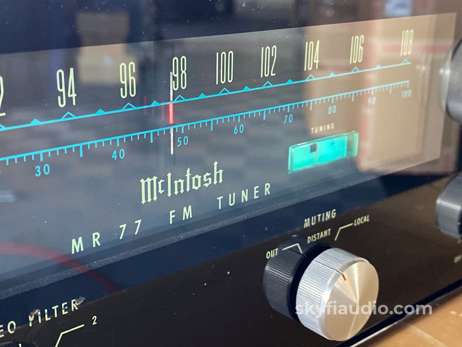
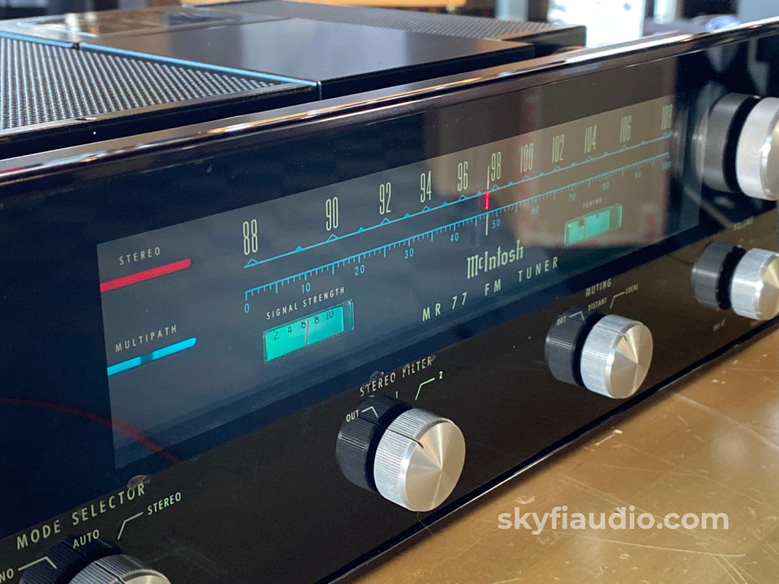
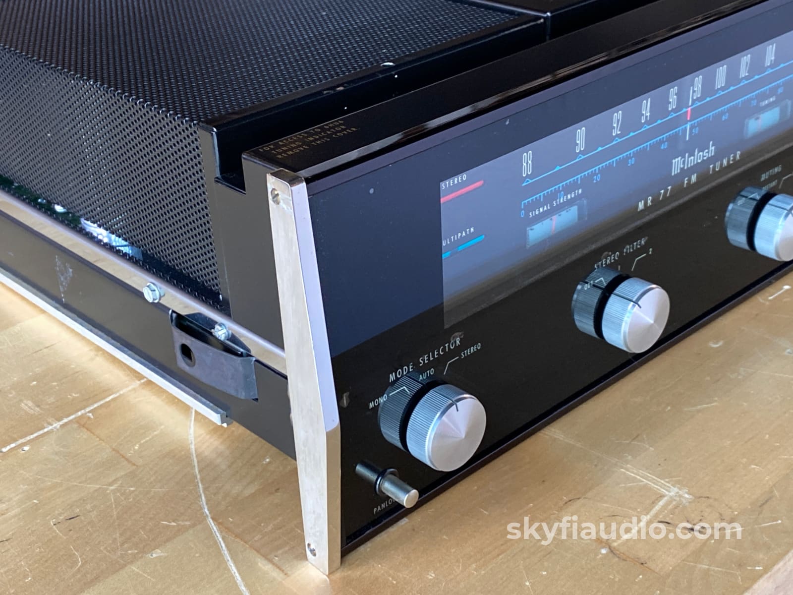
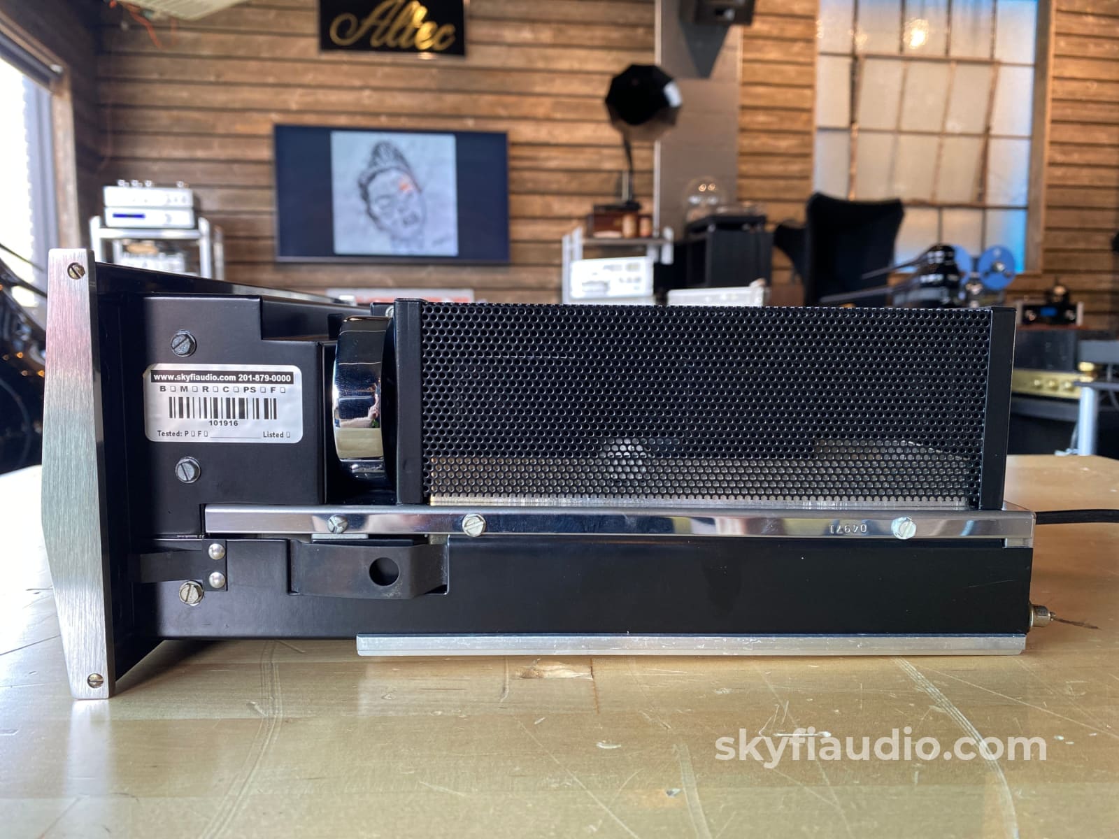
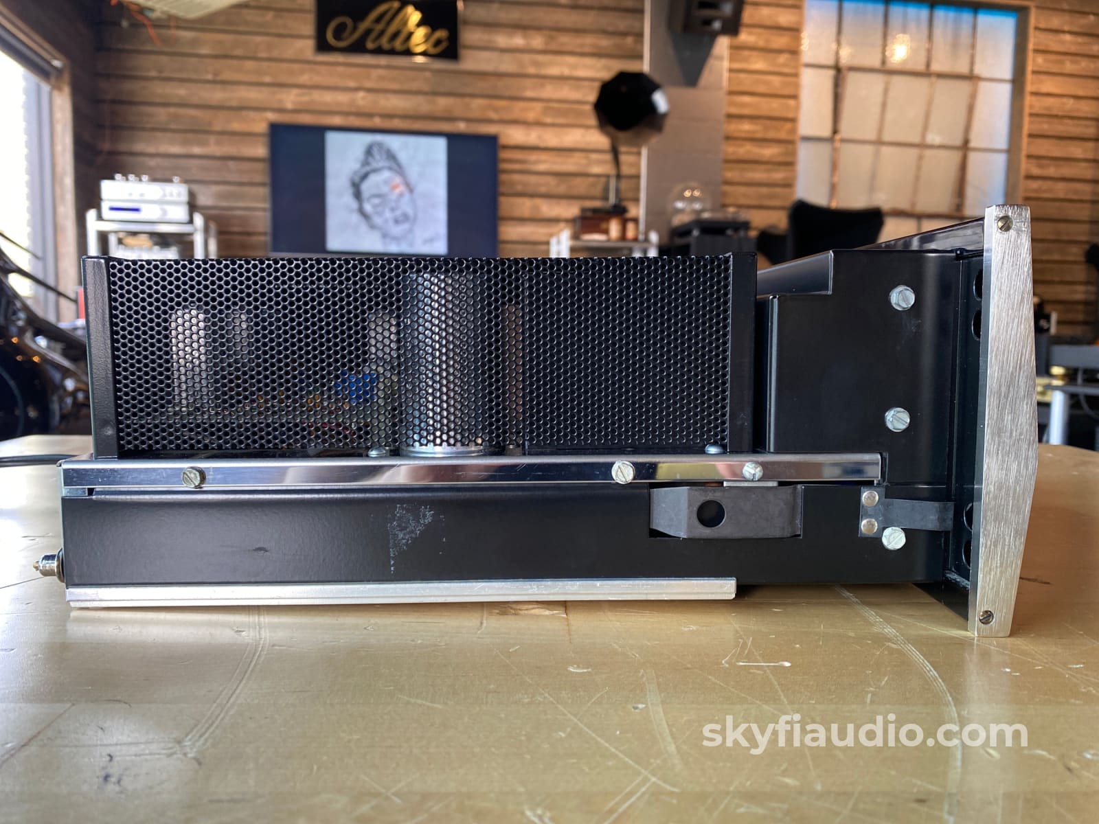
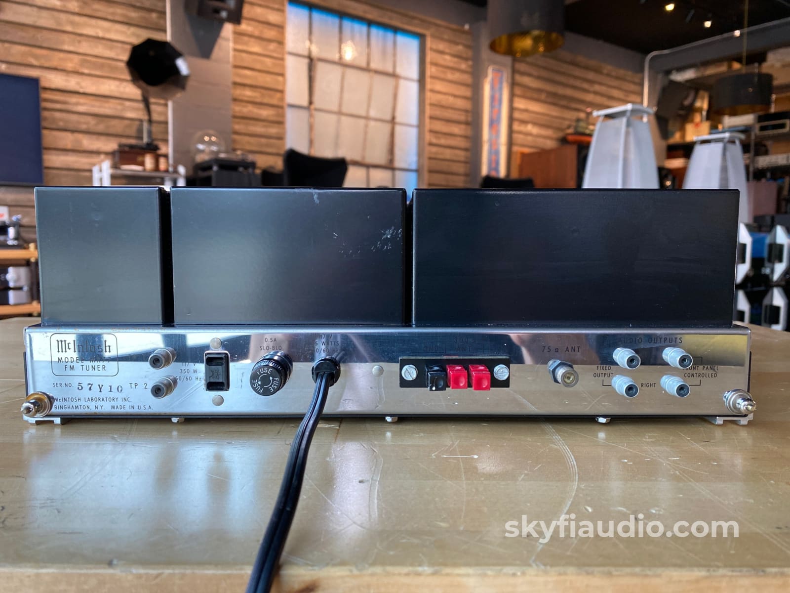
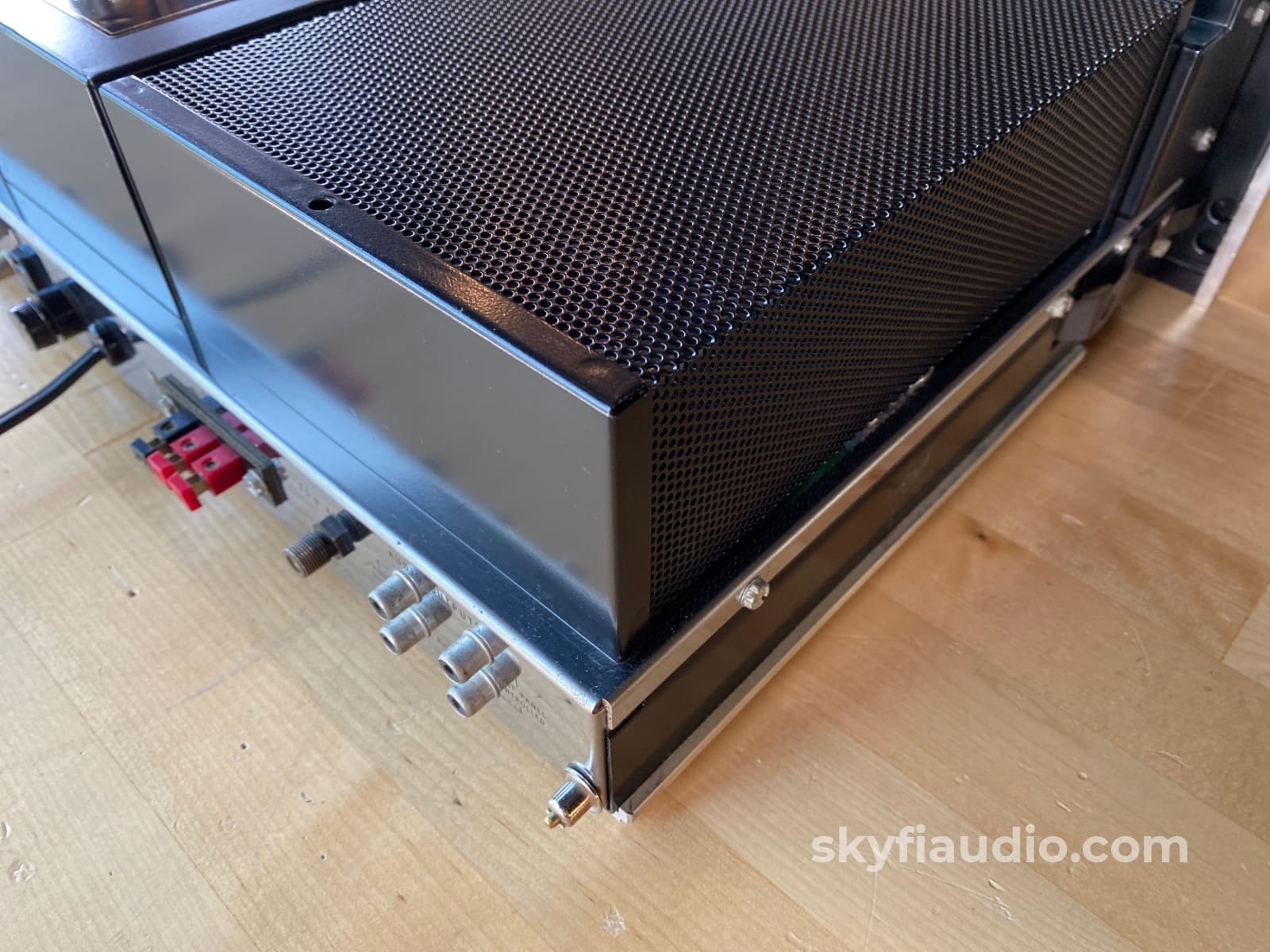
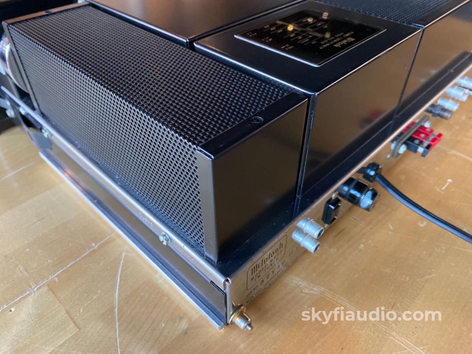
McIntosh MR77 Vintage FM Tuner
Free Shipping on Most Electronics - Excludes Speakers and Items Requiring Freight - Contiguous U.S. Only
Pickup currently unavailable at SkyFi 479

McIntosh MR77 Vintage FM Tuner
SkyFi 479
479 South Broad Street
Glen Rock NJ 07452
United States
General:
If you haven't heard a vintage FM tuner recently, you really owe it to yourself to give one a listen.
The right model matched with the proper antenna will make some of the warmest and most natural sounding music you've (ever) heard. Especially through an all analog piece like this McIntosh MR77.
We are very lucky in our area to have some of the best sounding stations in the world, and you better believe we take full advantage. If you come to our shop you're likely to hear our local Jazz station WBGO playing from one of our vintage tuners just like this one.
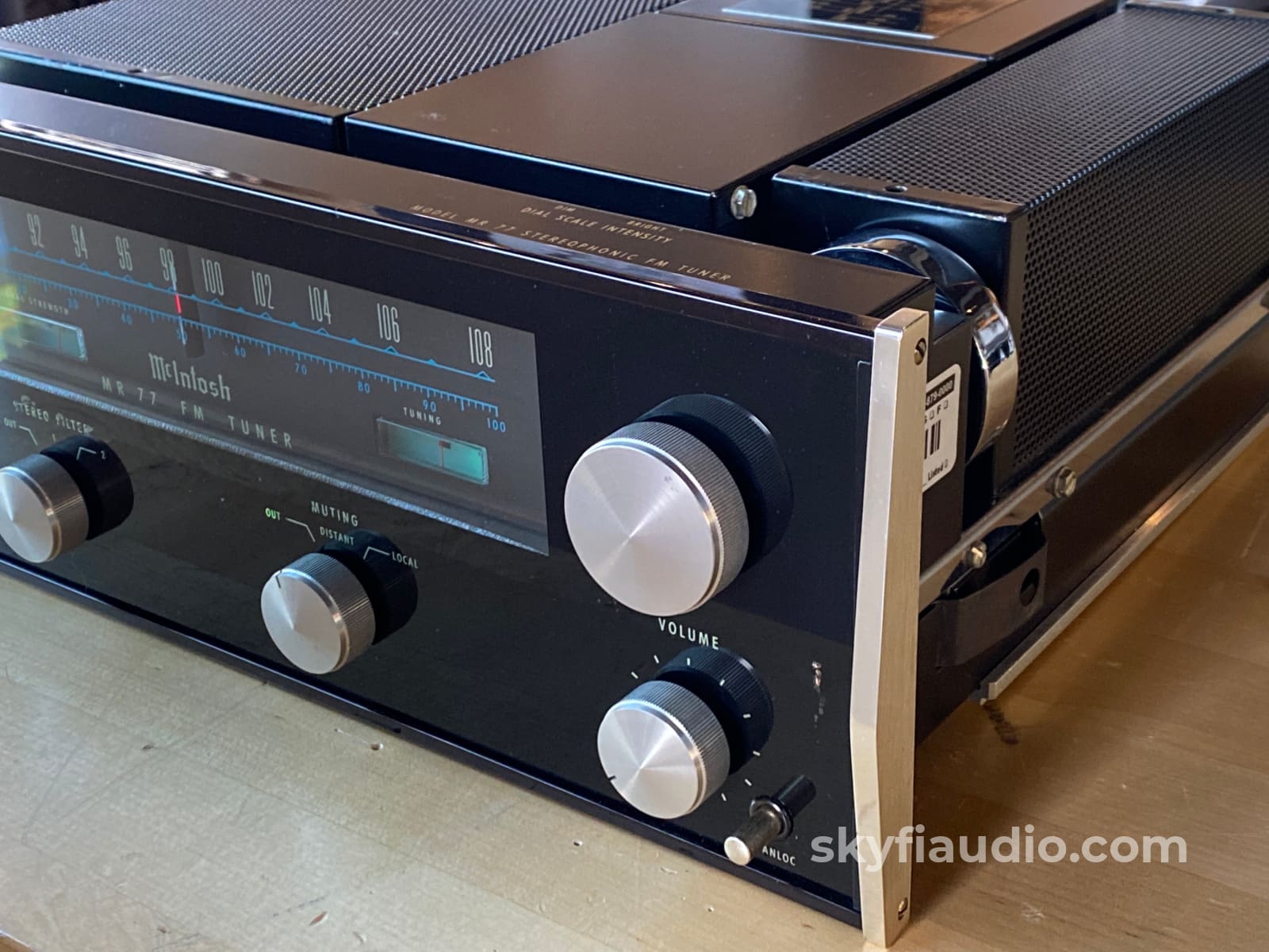
Sitting just below the renowned McIntosh MR78, this MR77 model provides 99% of the sound quality with a just a few removed features, which most users would never ever use or miss.
My favorite feature (that's actually not found in the MR78!) is the "magic eye" indicator. It's an actual tube-based light emitting component with two lines that fluctuate indicating multipath reception. Super cool!
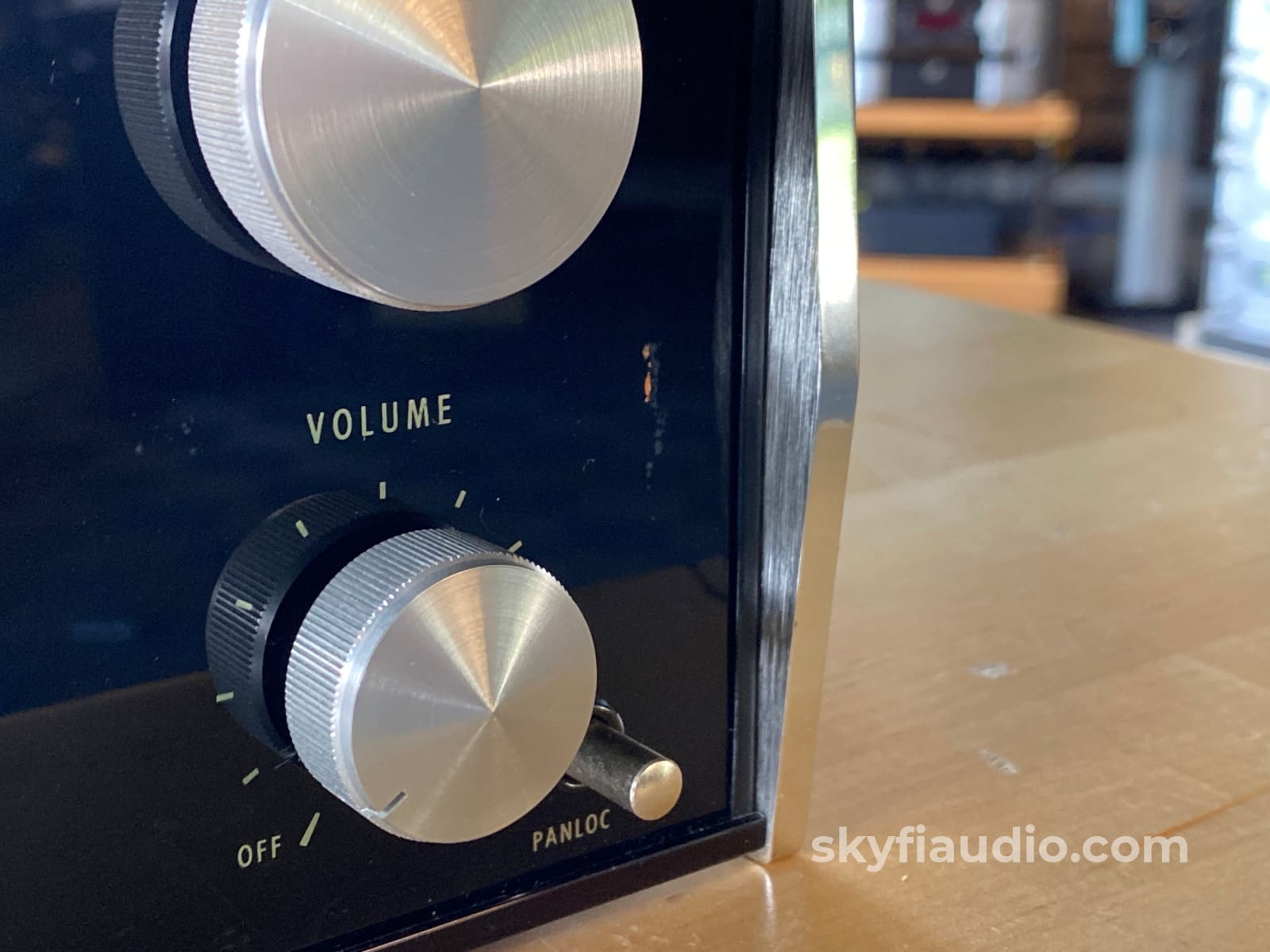
Condition is very good with only the slightest signs of use.
Thoroughly tested in our lab utilizing our Sencore SG80 FM Generator, which allows us to generate a reference FM signal of any frequency and amplitude, and then measure the results of the MR77 tuner output on our Sencore PR81 or oscilloscope. This unit passed with flying colors and produced a natural and warm sounding output.
Cosmetic Notes:
• Light blemishes on metal surfaces and covers
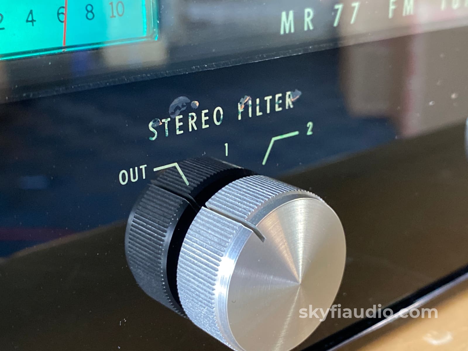
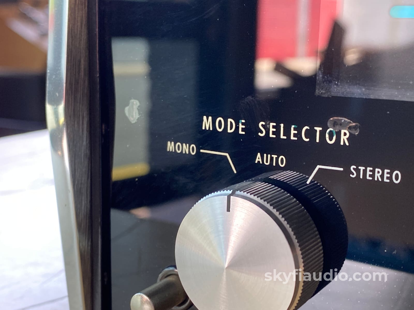
• Glass has a few defects and some of the lettering is worn
Recommended Cables:
Kimber Kable - RCA Interconnects - Better
Kimber Kable - RCA Interconnects - Best
The SkyFi Testing Process for Tuners:
We start with a visual inspection of all internal components to make sure that there are no signs of heat stress or damage. Capacitors are checked for telltale signs of predictive failure including bulging, shrunken wrappers, or physical leakage. We also inspect the PCBs for discoloration from resistors or transistors that may have been running hot. On vintage units we often spot check select capacitors for value and ESR. Vintage analog tuners also have moving parts related to the tuning gang and dial string. These parts are inspected for smooth operation.
If the unit passes visual inspection it is bench tested for a handful of key performance parameters using a Sencore SG80 AM/FM Stereo Analyzer. The SG80 allows us to “simulate” an ideal radio station using precision test signals instead of music. This device, in conjunction with an oscilloscope allows us to properly evaluate the following parameters:
1. AM Reception (Where Applicable)
2. FM Mono Reception & Tuning Meter Function
3. FM MPX Reception (Stereo)
4. Dial Tracking - How accurately the tuner dial or display indicates the actual frequency of the broadcast being received.
5. Stereo Separation - A properly working stereo tuner will have minimal crosstalk between the left and right channel.
6. Sensitivity & Signal Strength Meter Function - By lowering the output of the SG80 we can simulate weak stations and determine how well the tuner will be able to pull in weak distant stations. This adjustment also helps us verify signal strength meter function.
If the tuner has acceptable performance related to the parameters above we connect the unit for listening tests with a simple dipole antenna. We listen for audio reproduction quality of local stations and evaluate how many stations the tuner can receive while we sweep through the dial. We are looking to verify that the tuner can decode stereo on strong local broadcasts and pick up a wide variety of local stations at the bottom, middle, and top of the frequency band. At this point we also test convenience features such as muting, filters, built in oscilloscope function, etc.
We finish up with an extended listening test on our long term test rig. We tune in a strong local station and monitor for drift over a 2-3 hour period.
Manual:
Click here for a PDF copy of the MR77 Owner's Manual
Technical Specifications:
SENSITIVITY:
2μV for 35 dB of quieting; 2.5μA at 100% modulation (±75 kHz deviation) for 3% total noise and harmonic distortion
SIGNAL TO NOISE RATIO:
75 dB below 100% modulation
HARMONIC DISTORTION:
0.2% mono or stereo at 100% modulation, 20 Hz to 15,000 Hz. Typically, 0.05% at 1,000Hz
DRIFT:
25,000 Hz in first two minutes; thereafter 5,000 Hz at 25°C in 24 hours
FREQUENCY RESPONSE:
±1 dB 20 Hz to 15,000 Hz with standard de-emphasis, (75μS) and 19,000 Hz pilot filter
CAPTURE RATIO:
0.25 dB detector only; 2.5 dB complete tuner
SELECTIVITY:
Adjacent channel 6 dB IHF, carrier 47 dB down; Alternate channel 50 dB IHF, carrier 90 dB down
SPURIOUS REJECTION:
100 dB IHF
IMAGE REJECTION:
100 dB; 88 to 108 MHz (IHF)
MAXIMUM SIGNAL INPUT:
12 volts across 300 ohms antenna terminals will not increase harmonic or intermodulation distortion
INTERMODULATION DISTORTION:
0.2% mono or stereo for any combination of frequencies from 20 Hz to 15,000 Hz with peak modulation equal to 100% or less. Typically 0.1%
AUDIO HUM:
75 dB down from 100% modulation
MUTING:
70 dB noise reduction between stations
MUTING THRESHOLD:
Position 1; 5 μ V ; Position 2, 20μV
SCA FILTER:
50 dB down from 67 kHz to 74 kHz; 275 dB per octave slope
STEREO SEPARATION:
40 dB at 1,000 Hz
STEREO FILTER:
10 dB noise reduction in position 1
20 dB noise reduction in position 2
ANTENNA INPUTS:
300 ohms balanced; 75 ohms un- balanced
AUDIO OUTPUT:
2.5 volts into 47,000 ohms; 1 volt into 600 ohms from fixed output
POWER REQUIREMENT:
120 volts, 50/60 Hz. 35 watts
IF SYSTEM:
8-Pole Rimo Filter, 2 IC's, 1 J-Fet, and push-pull overlay power transistor stage driving a linear phase bridge discriminator
STEREO INDICATOR:
Front panel stereo light activated by 19,000 Hz only
AUTOMATIC MONO-STEREO SWITCH:
Mclntosh developed; all electronic automatic mono-stereo switching circuit
SEMICONDUCTOR COMPLEMENT:
21 Transistors, 24 Diodes, 4 Integrated Circuits, 1 Indicator Tube
SIZE:
Front panel measures 16 inches wide (40.64 cm) by 5-7/16 inches high (13.81 cm). Chassis measures 15 inches wide (38.1 cm) by 13 inches deep (33.02 cm), including PANLOC shelf and back panel connectors. Knob clearance required is 11⁄2 inches (3.81 cm) in front of mounting panel
FINISH:
Front panel is anodized gold and black with special Mclntosh gold/teal panel nomenclature illumination. Chassis is chrome and black
MOUNTING:
Exclusive Mclntosh developed professional PANLOC
WEIGHT:
27 pounds (12.25 kg) net, 39 pounds (17.69 kg) in shipping carton
|
Item |
Included |
|
Original Box |
Not Included |
|
Manual |
Yes and Online |
|
Remote |
Not Applicable |
|
Cables |
Yes - Power Only |
|
Physical Condition |
7 / 10 |
|
Working Condition |
10 / 10 |
Choose options


