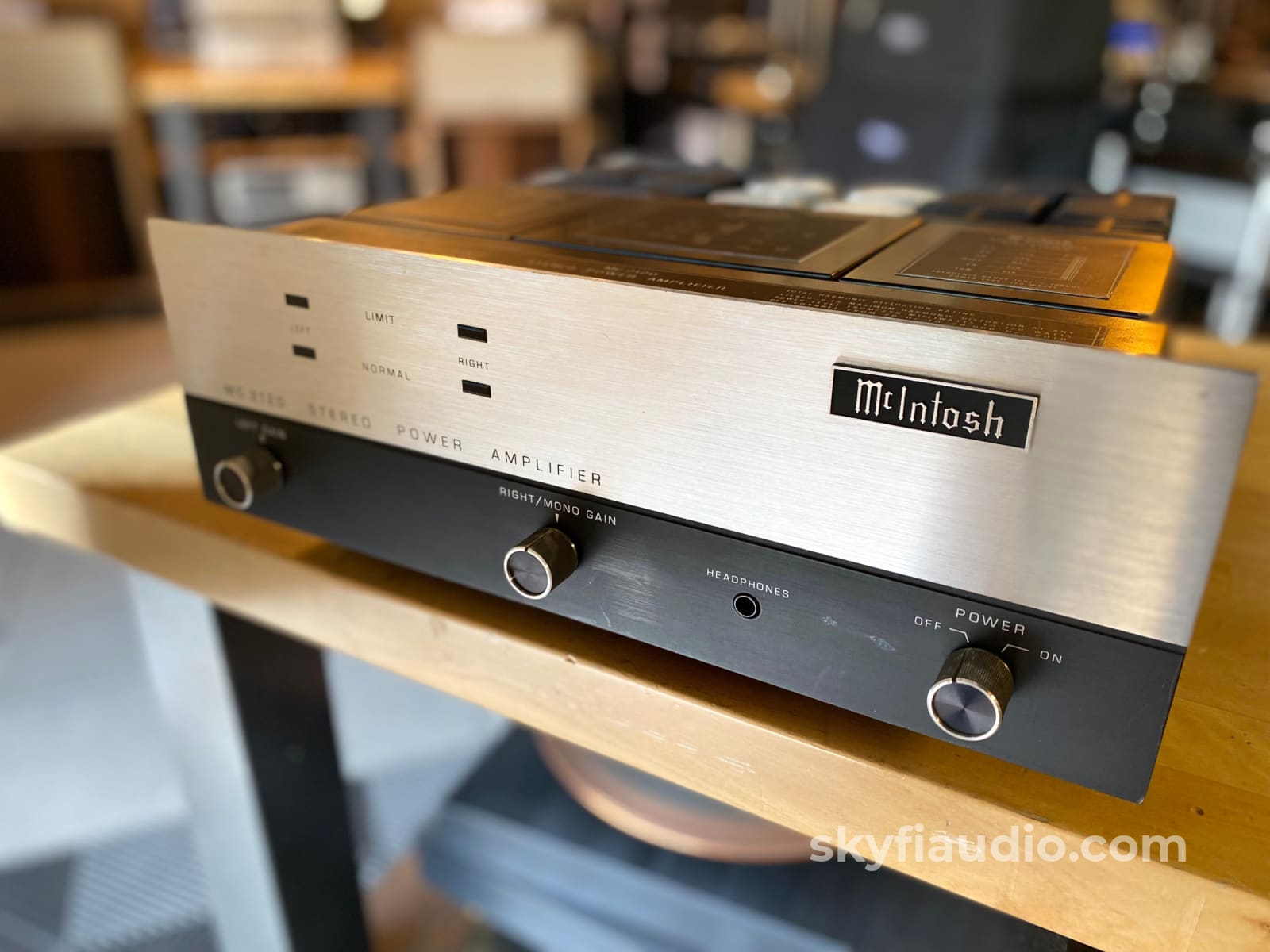
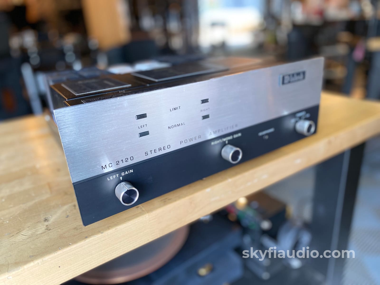
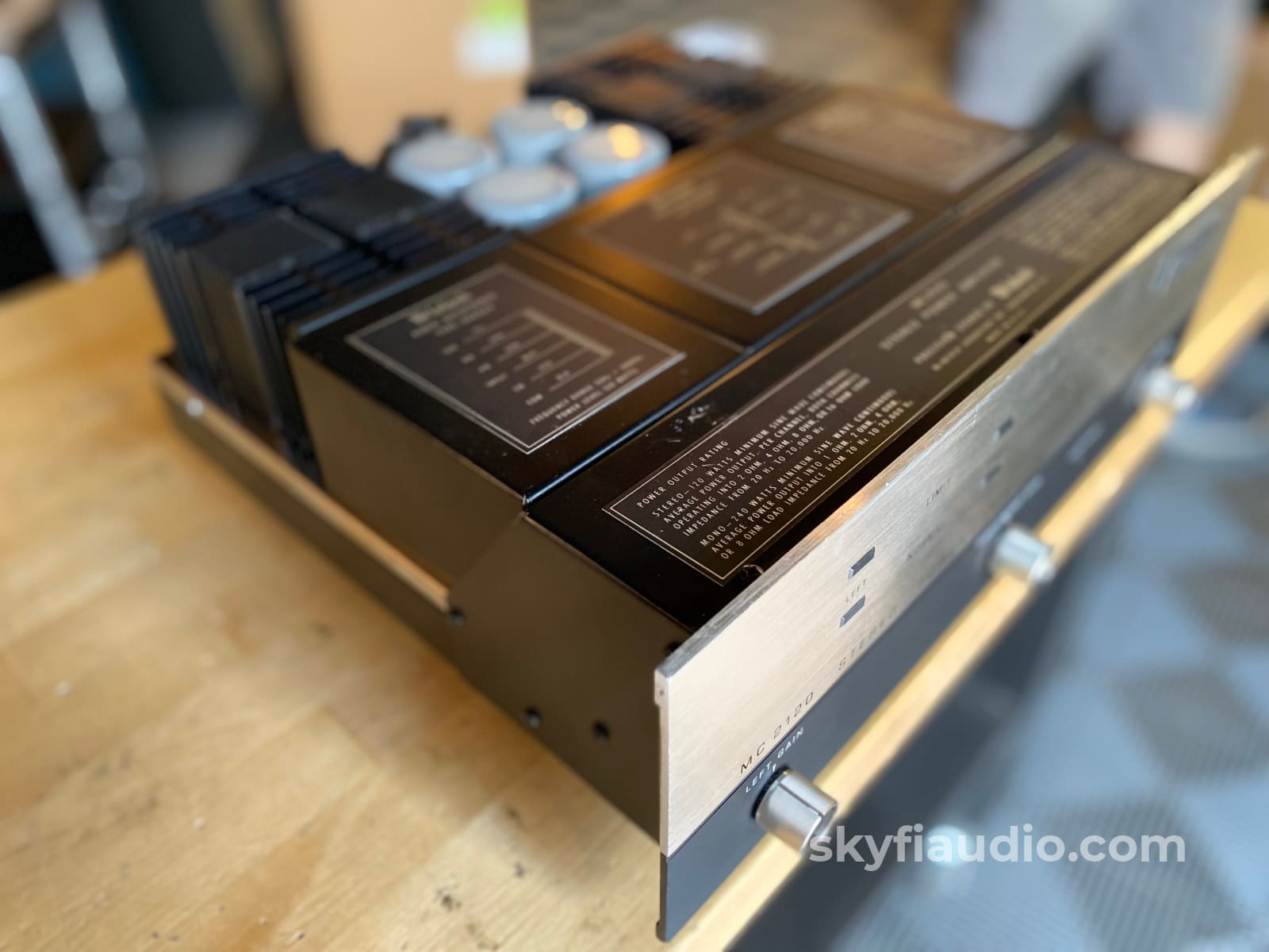
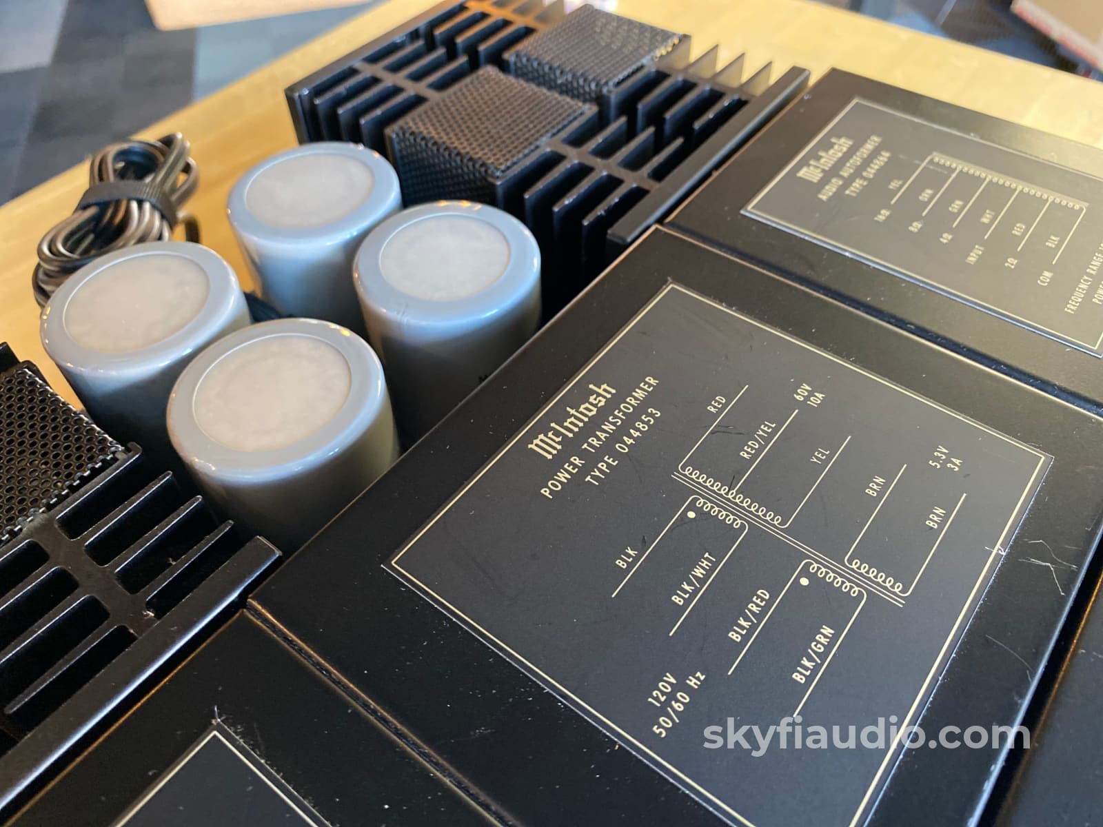
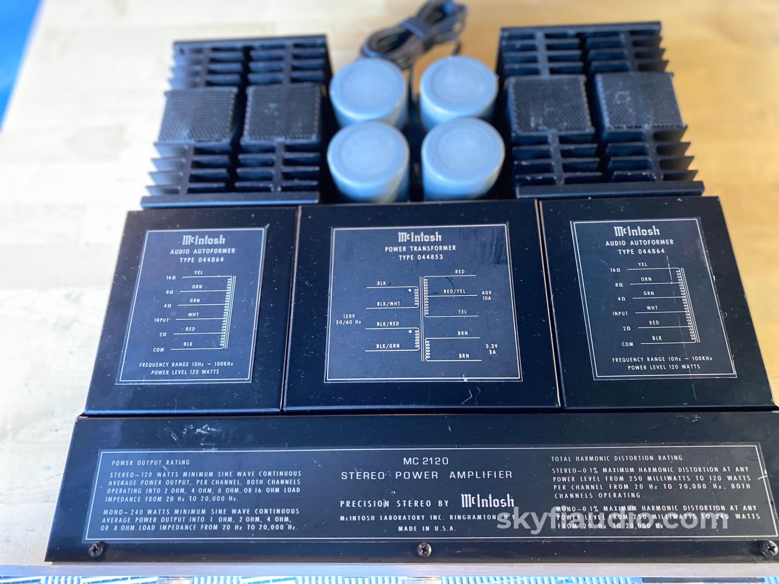
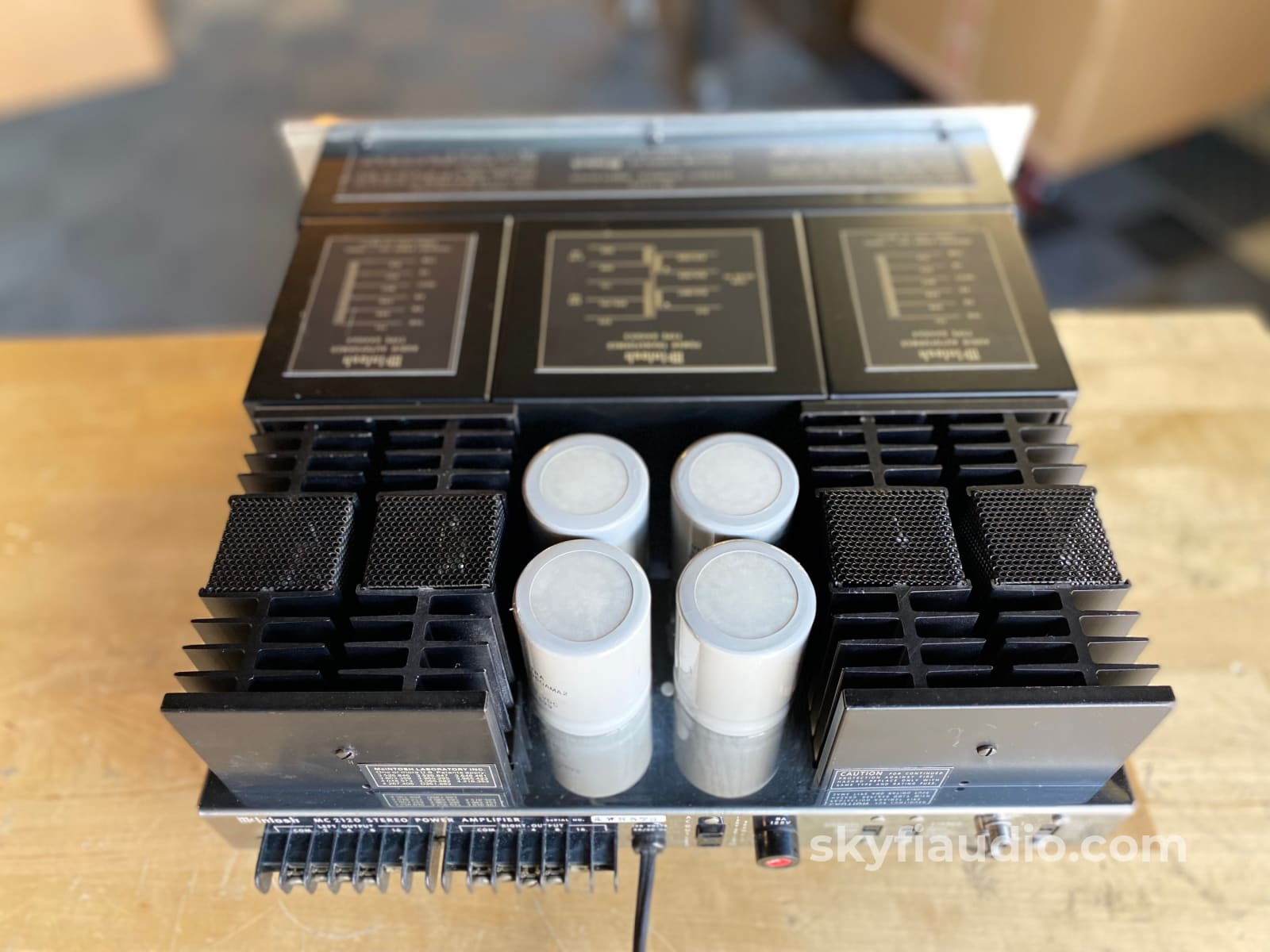
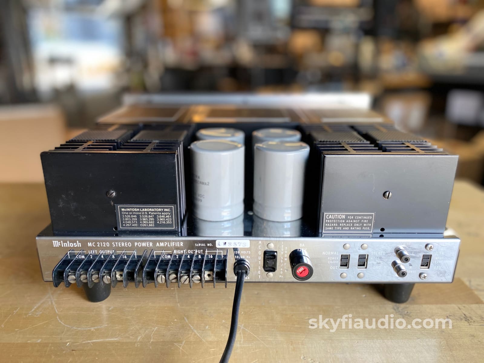
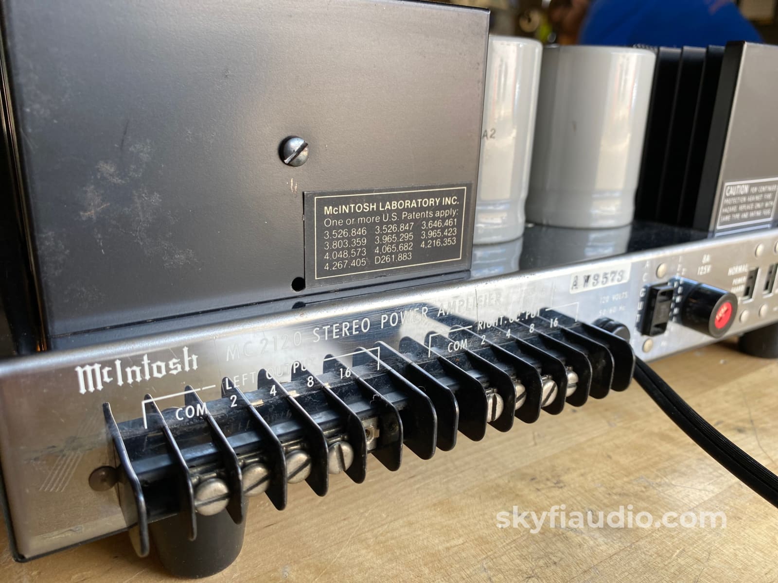
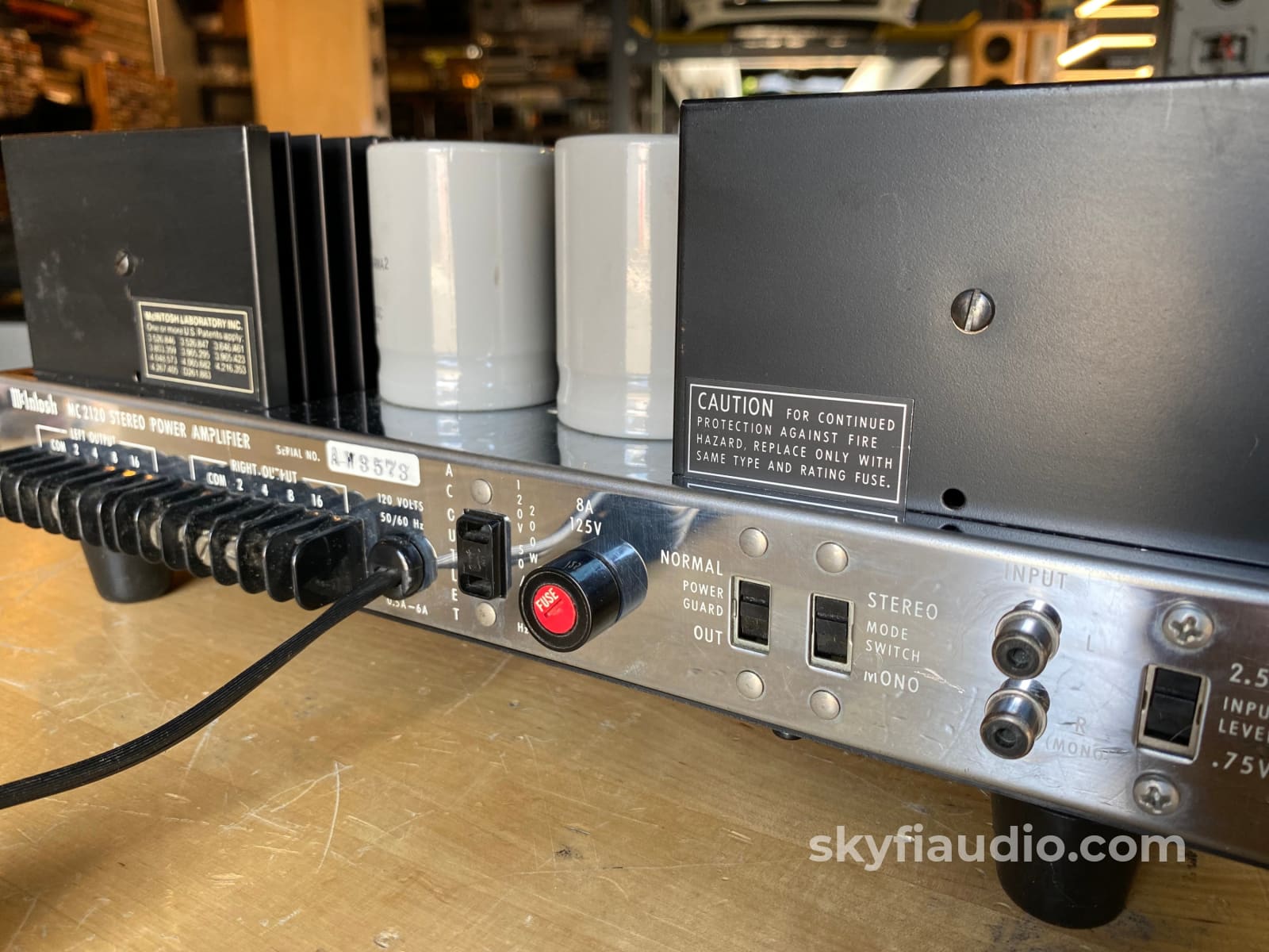
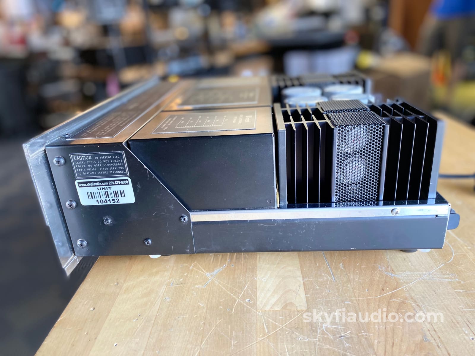
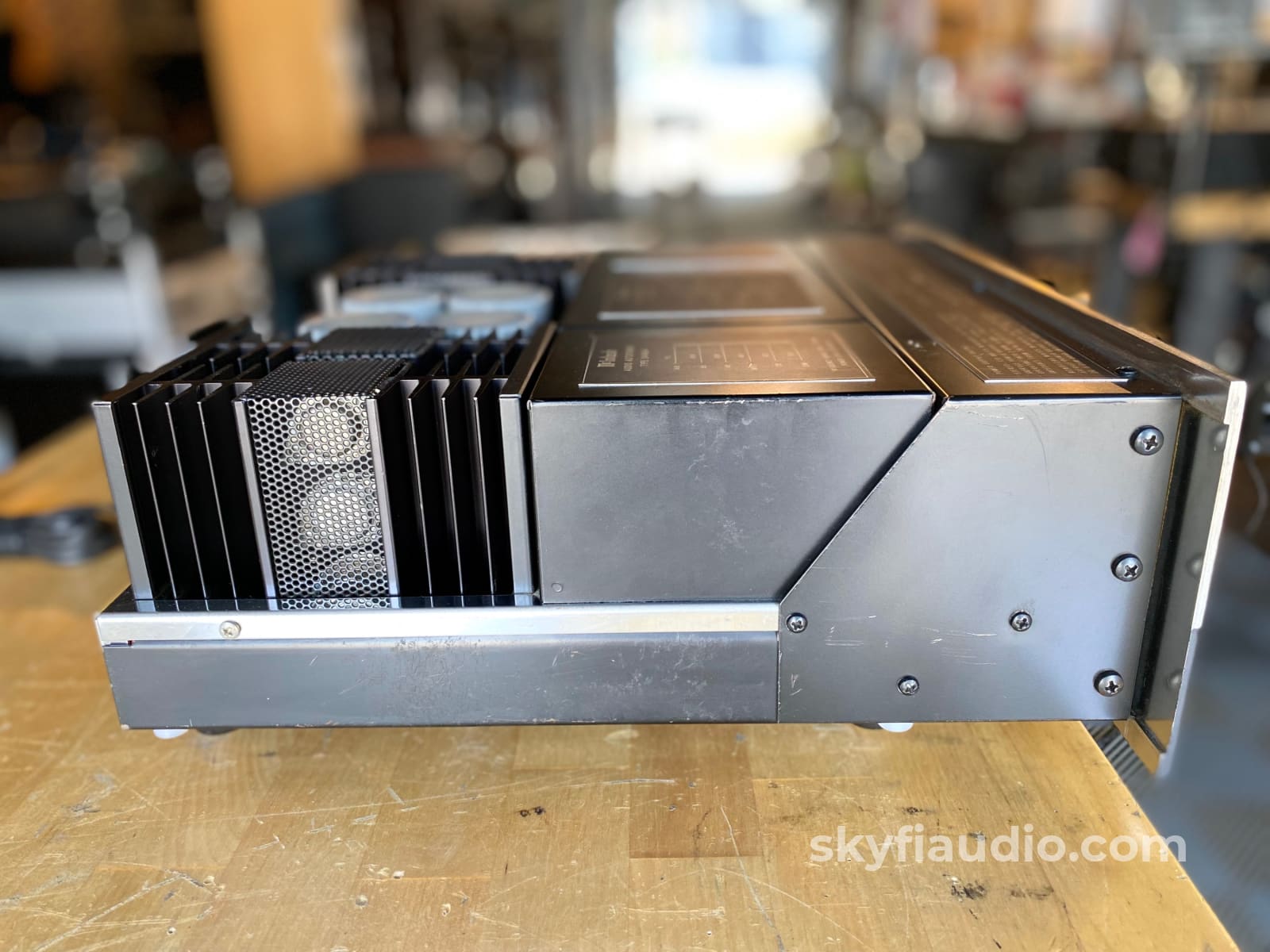
McIntosh MC2120 Solid State Vintage Amplifier
Free Shipping on Most Electronics - Excludes Speakers and Items Requiring Freight - Contiguous U.S. Only
Pickup currently unavailable at SkyFi 479

McIntosh MC2120 Solid State Vintage Amplifier
SkyFi 479
479 South Broad Street
Glen Rock NJ 07452
United States
General:
Super nice second generation solid state amp from McIntosh made in the 1980's
Same internals as the MC2125 but sans meters, giving it a more modern look and a better cosmetic match to great preamps like the C22 without as much glass.
Best of all it uses autoformers, a key to the coveted McIntosh signature sound which was omitted due to cost savings in the 1990's.
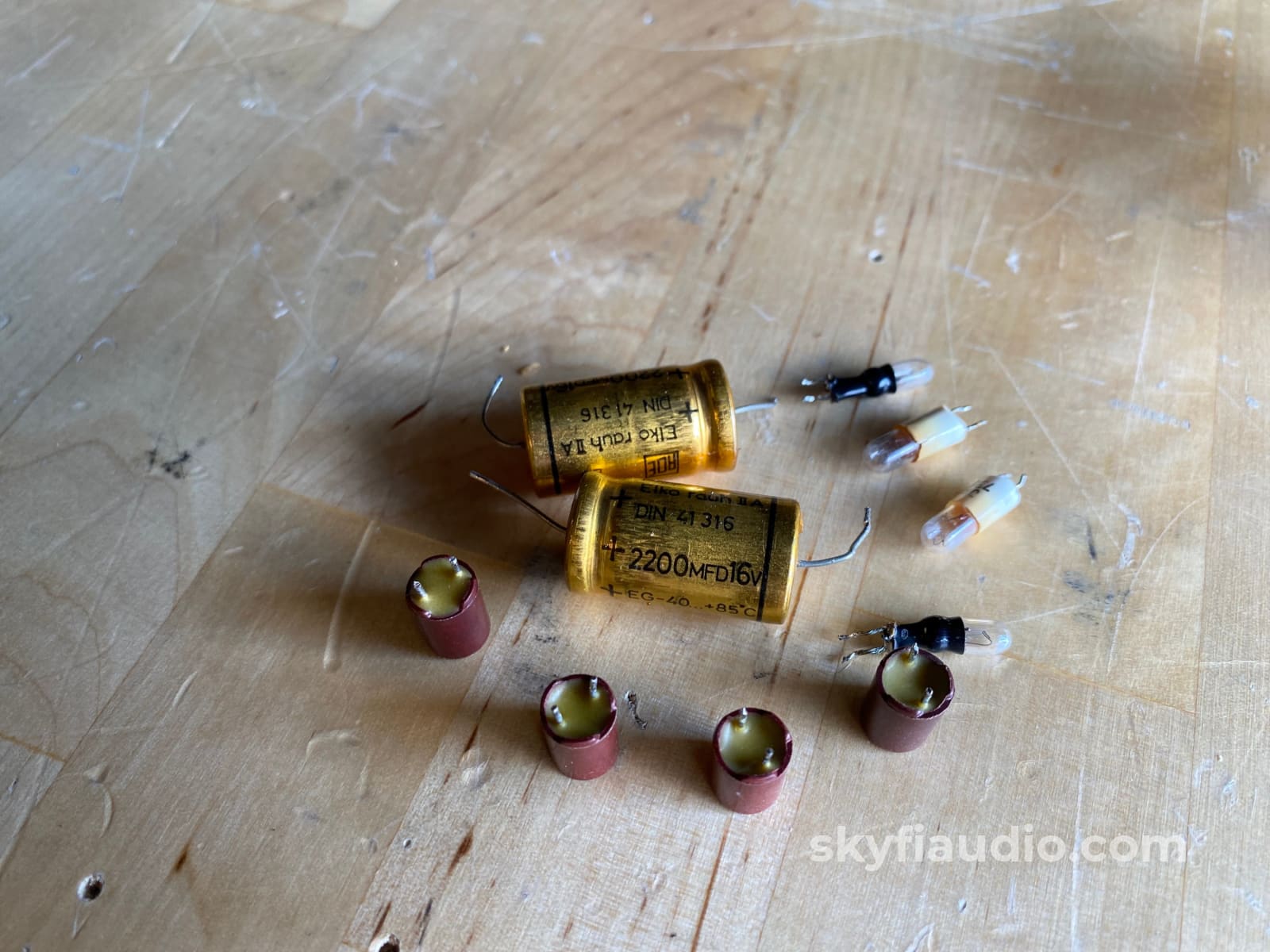
This MC2120 was serviced in house and is working as it should. We replaced a few critical parts and did a bit of preventive maintenance to ensure a long future life.
Cosmetic Notes:
• Faceplate shows some scratches and wear
• Various blemishes to all metal surfaces
Service Notes:
• Rotary volume controls replaced
• All controls cleaned
• Relay cleaned
• Lamps replaced
• Aging foam replaced
More on the MC2120 found online:
A stereo power amplifier equipped with a power guard system unique to McIntosh.
The Power Guard System is a circuit realized by a waveform comparison circuit originally designed by McIntosh. It electrically compares the output waveform with the input waveform. When the waveform difference reaches 0.5%, the Limit lamp lights and the Normal lamp goes off. When the waveform difference reaches 1%, the Power Guard circuit operates to prevent clipping of the amplifier, to prevent distortion from reproducing from the speaker, and to protect the speaker.
The input and output waveforms are compared by an IC differential amplifier, and the waveform difference due to distortion of the output waveform is converted into a voltage. This voltage is amplified approximately 100 times, passed through a full-wave rectifier circuit, and supplied to a Schmidt trigger circuit. This voltage activates the power guard circuit and activates the power guard circuit when the voltage rises above the level that turns on the Limit lamp.
The Limit lamp is designed to light up when the amplifier is overloaded, and is lit for a visible period of time, even when the overload condition is very short. In this case, the meter will display 200W.
When using a Power Guard circuit, the Power Guard switch on the rear panel must be set to Normal. Even when this switch is in the out position, only the Limit lamp is active.
The output signal of the amplifier is fed through an output transformer, which is designed to match the output terminal of any impedance and provides the maximum output for all frequency signals regardless of which output terminal is used.
The transformer also protects the speakers in the event of an amplifier failure. For example, if a DC component is mixed into the output, the transformer eliminates the component and prevents damage to the speakers.
To prevent overloading of the output transistor, the output signal is always monitored by a monitor circuit, which becomes high impedance when the output level exceeds the rated value. When the output reaches its maximum value, the monitor circuit limits the signal supplied to the output transistor to prevent damage to the output transistor.
The input side of the power amplifier section uses a monolithic transistor differential amplifier with low noise to eliminate distortion. The input signal and feedback signal are supplied to the differential amplifier. The next stage circuit is a voltage amplifier circuit that operates at class A. The driver circuit and the complementary service circuit are used to reduce crossover distortion by operating close to class A. The circuit is designed to be biased appropriately against temperature changes at all times.
The power transistor is class AB operation and the bias current is kept safe by thermistors. The output circuit is a single-ended para-push type and consists of six highly reliable complementary service power transistors. This circuit is balanced emitter-follower coupling and is stable with less distortion. In addition, the unique output-bias circuit provides class B operation with no crossover distortion.
Brand Background:
McIntosh Laboratory is an American manufacturer of handcrafted high-end audio equipment based in Binghamton, New York. The company was founded in 1949 by Frank McIntosh. The company designs and produces audio amplifiers, stereo tuners and other consumer electronics products.
Ownership:
Single Owner
Connections:
RCA Inputs jacks, screw terminals for speakers, captive power cord
General Sound:
Neutral sound with little to no coloration
Cosmetic Condition:
7/10 = Good. One or two minor scratches. Well Maintained.. See our detailed rating description here.
Working Condition:
Working perfectly and tested in our lab and listening room.
Included:
Just the unit and power cord.
Packing:
Manufacturers Packing
Specs:
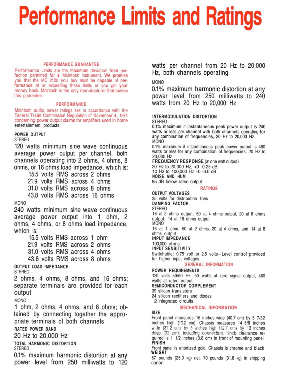
Please see the linked manual or last photo
Dimensions:
Front panel measures 16 inches wide (40.7 cm) by 5-7/32 inches high (13.2 cm).
Chassis measures 14-5/8 inches wide (37.2 cm) by 5 inches high (12.7 cm) by 13 inches deep (33 cm), including connectors. Knob clearance required is 1-1/2 inches(3.8 cm) in front of mounting panel.
Weight:
57 pounds (25.9 kg)
Approximate Age:
1980
Link to Manual:
Click Here
Recommended Cables:
Kimber Kable - RCA Interconnects - Better
Kimber Kable - RCA Interconnects - Best
Kimber Kable - Speaker Cables - Better
Kimber Summit Series Monocle XL Speaker Cables (PAIR) - Best
Kimber Summit Series BiFocal XL Bi-Wire Speaker Cables (PAIR) - Best If Applicable
Kimber Kable - Power Cords - Better
Kimber Kable - Power Cords - Best
Testing Process:
We start with a visual inspection of all internal components to make sure that there are no signs of heat stress or damage. Capacitors are checked for telltale signs of predictive failure including bulging, shrunken wrappers, or physical leakage. We also inspect the PCBs for discoloration from resistors or transistors that may have been running hot. On vintage units we often spot check select capacitors for value and ESR.
If the amplifier passes visual inspection, we move on to a controlled power on sequence using a Sencore safety analyzer to monitor current draw in real time. Once the amplifier is determined to be safe to operate, we connect it to full AC mains for function and power testing. We connect the speaker outputs of the amplifier to a Sencore PA81 Power Analyzer which acts as a dummy load, DC offset monitor, and oscilloscope interface. We start with a low level 1KHz test signal at the amplifier’s input and slowly increase its amplitude while monitoring the output on an oscilloscope for signs of noise, clipping, distortion, or improper channel balance. We continue increasing the signal level until the amplifier reaches clipping. At this point we take an output power measurement and compare it to the spec sheet of the amplifier to verify proper performance. If the device under test has both balanced and single ended inputs they are both tested at this time. We finish off the bench evaluation with a 1KHz square wave check and a 20Hz to 20KHz sine sweep to assess the amplifier’s frequency response characteristics. This battery of tests will usually reveal if the amplifier has any issues that need further attention.
Before the device leaves the bench, we perform a listening test with actual music using a variety of preferred test tracks. Our benches are outfitted with familiar monitor speakers which help us identify inconsistencies that will not always show up on our test gear. The main things that we are listening for are hum or noise with no signal present, proper center image, clicks, pops, or any other obvious undesirable audio characteristics.
If the unit passes all of these tests it is moved to our long term testing rig where we simulate real word operating conditions for 6-8 hours. This allows us to monitor the unit for signs of thermal runaway or intermittent issues that only crop up when the unit has fully come up to temperature.
Choose options


