
Technics SU-8600 Vintage Integrated Amplifier - Light Service
Free Shipping (Contiguous U.S. Only)
Pickup currently unavailable at SkyFi 479
Technics SU-8600 Vintage Integrated Amplifier - Light Service
SkyFi 479
479 South Broad Street
Glen Rock NJ 07452
United States
General:
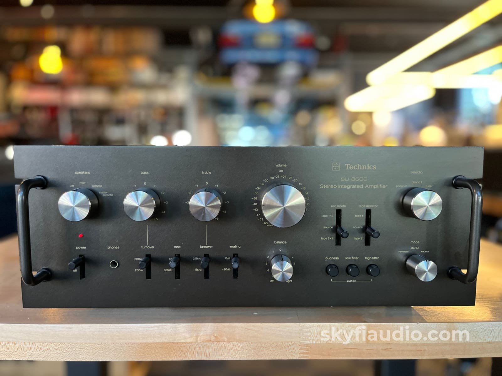
The Technics SU-8600 is a capable and high quality integrated amplifier from the mid to late 1970s. It produces 73 Watts into an 8ohm load perfect for driving most speakers to a comfortable level.
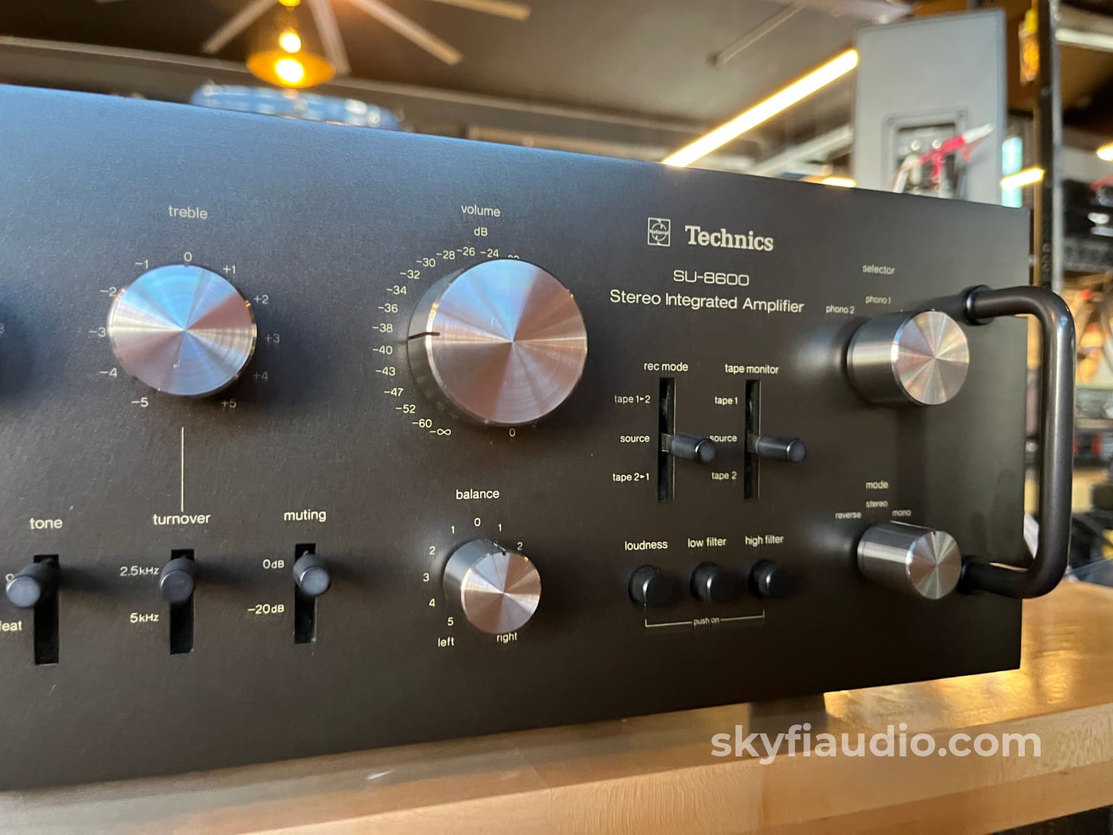
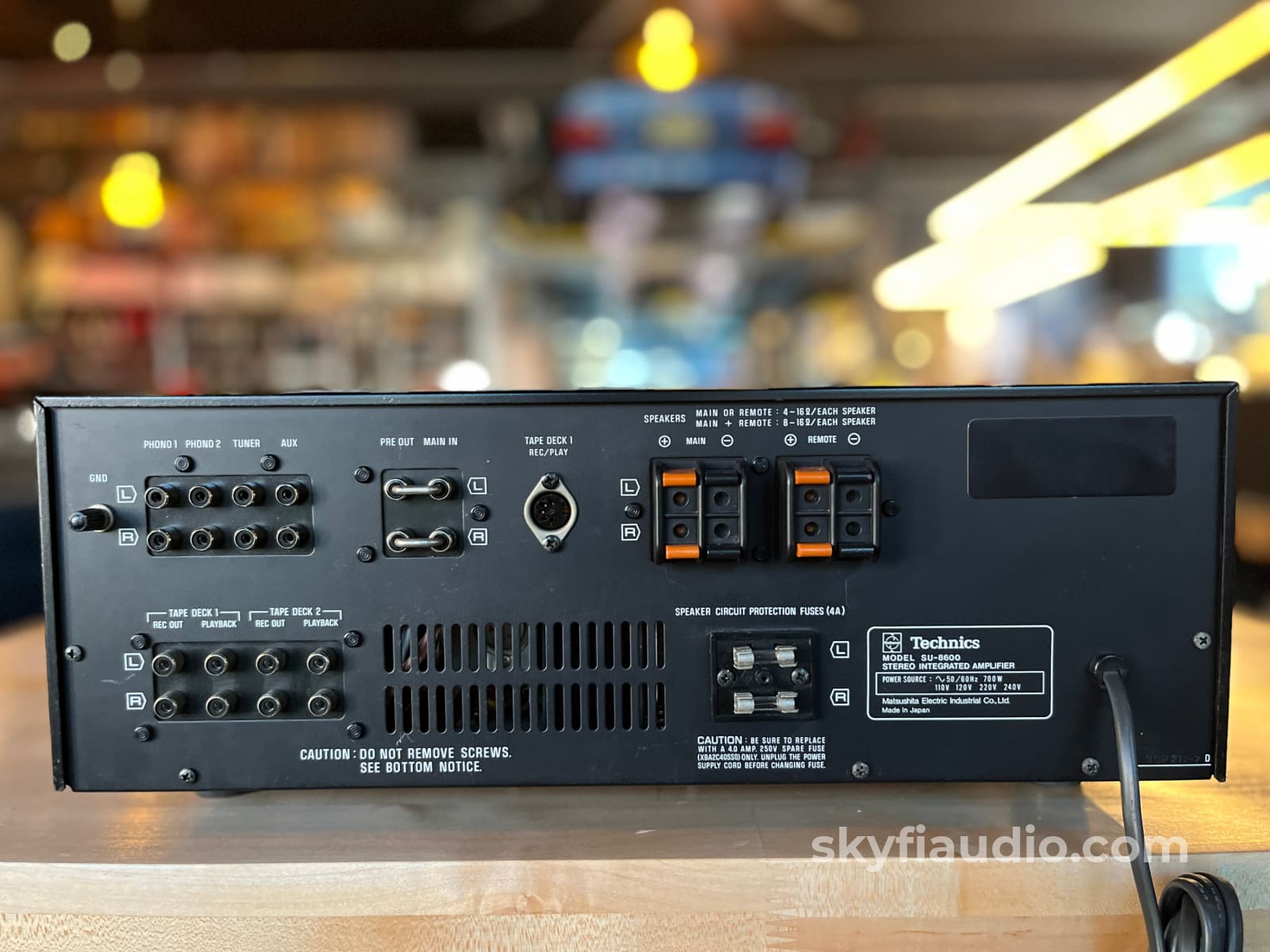
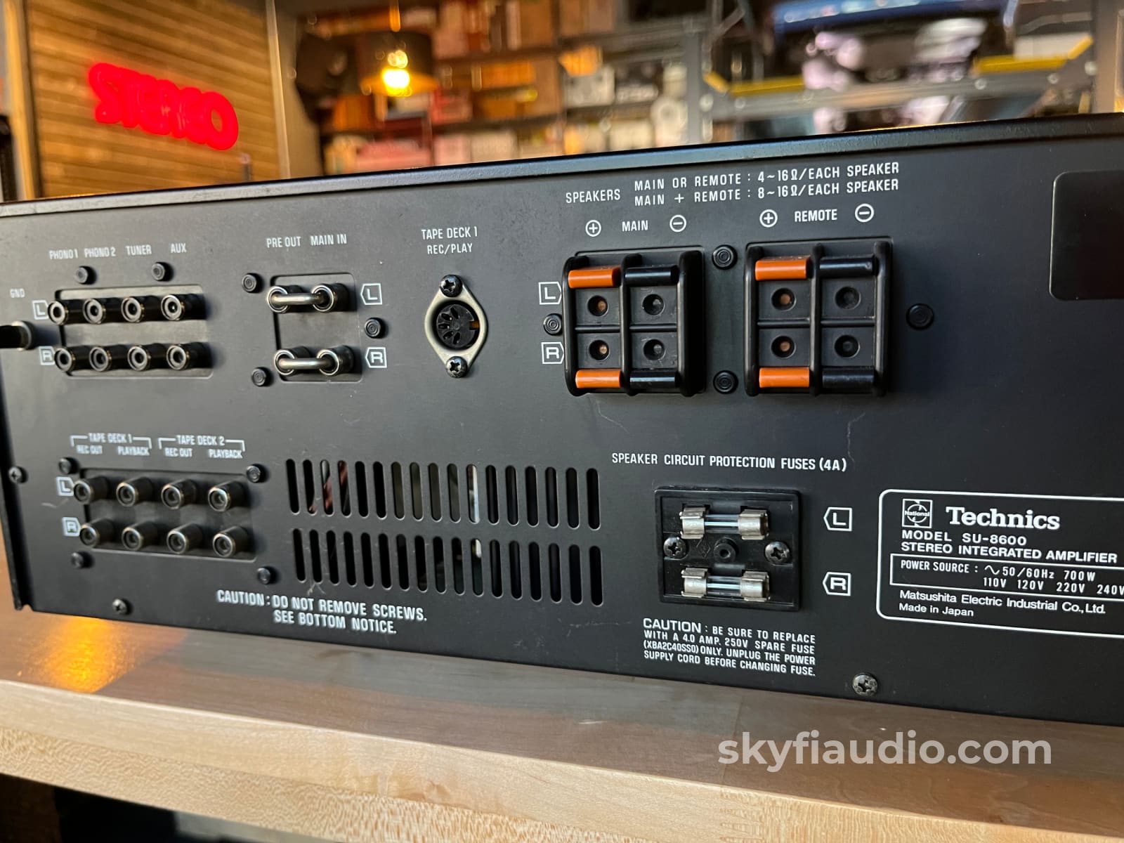
Standout features include dual phono inputs and dual tape loops. This makes the unit very valuable for the fan of analog sources!
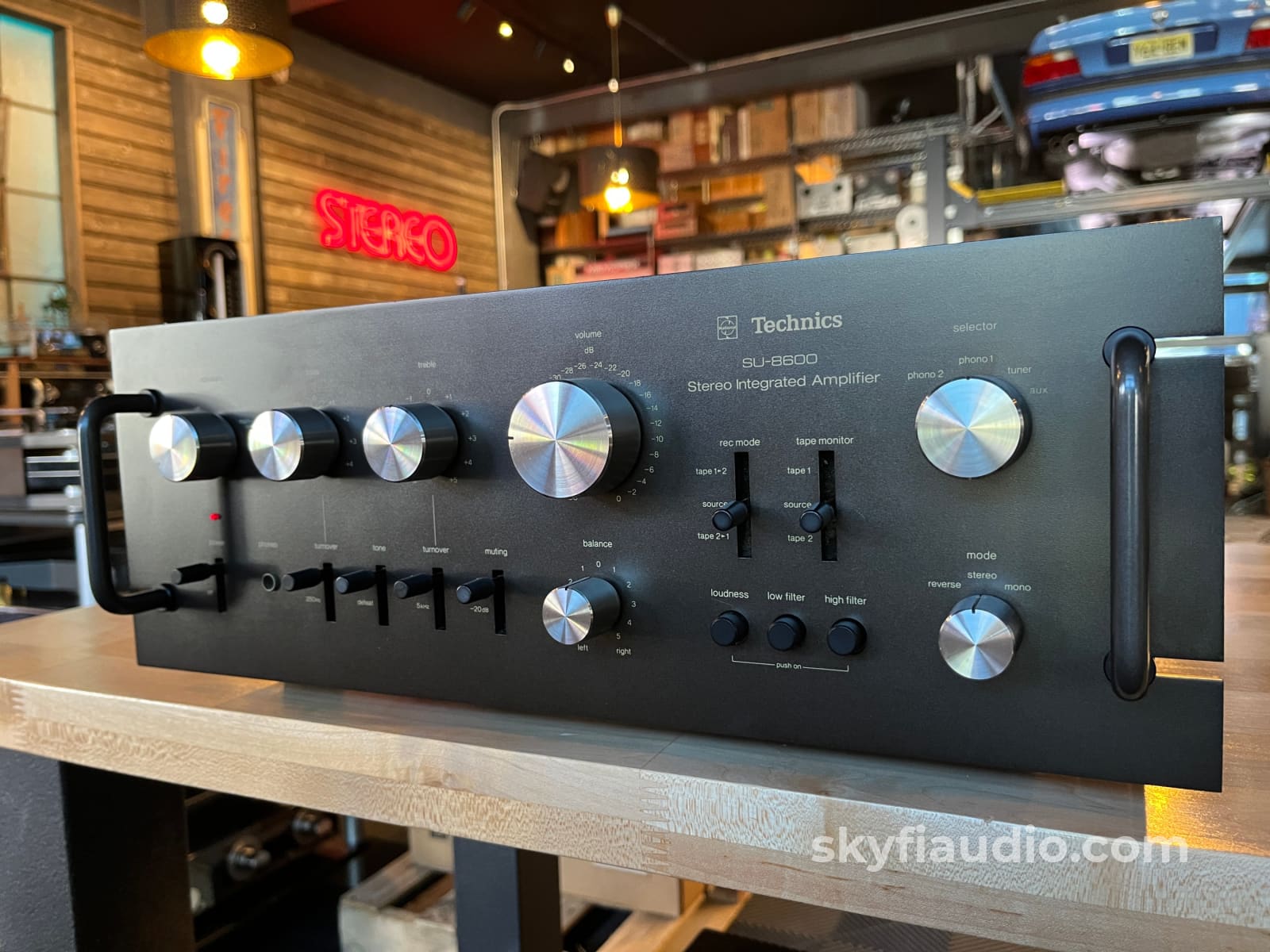
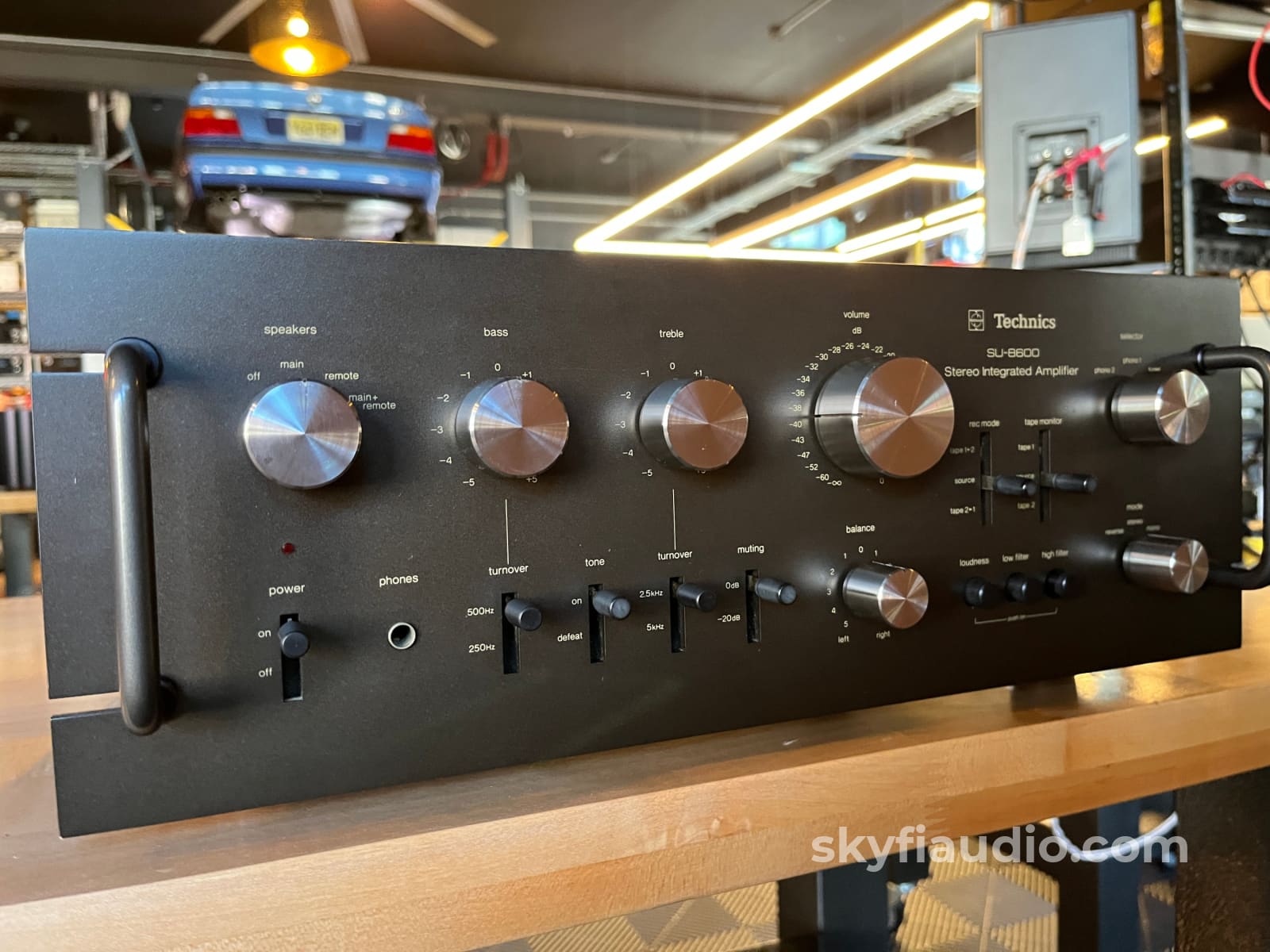
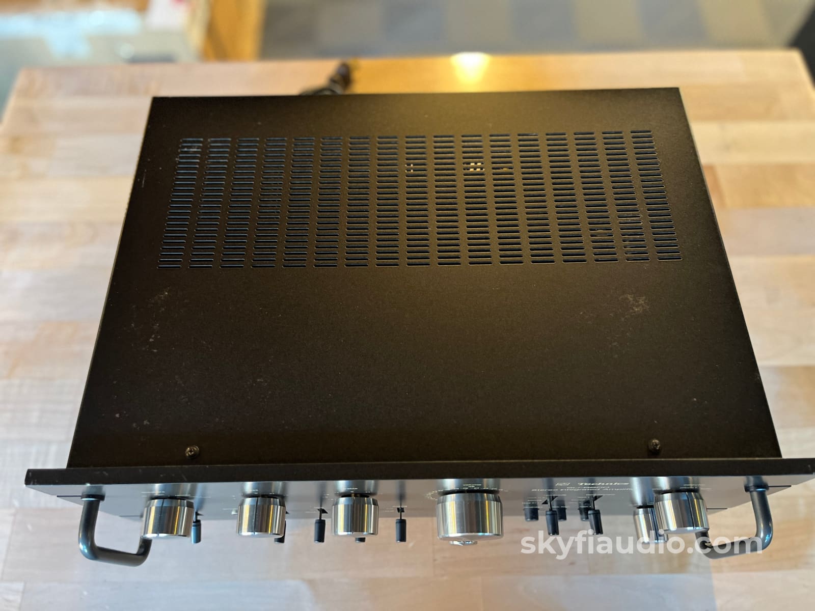
We also really like the industrial/professional look of this piece. The controls at front give you what you need without any of the fluff. It would look great paired with equipment of a similar aesthetic.
This integrated amplifier was also featured on the very cool website "thevintageknob" here.
It will come with to you in a custom packaged box so it will arrive safely.
SkyFi Cosmetic Notes:
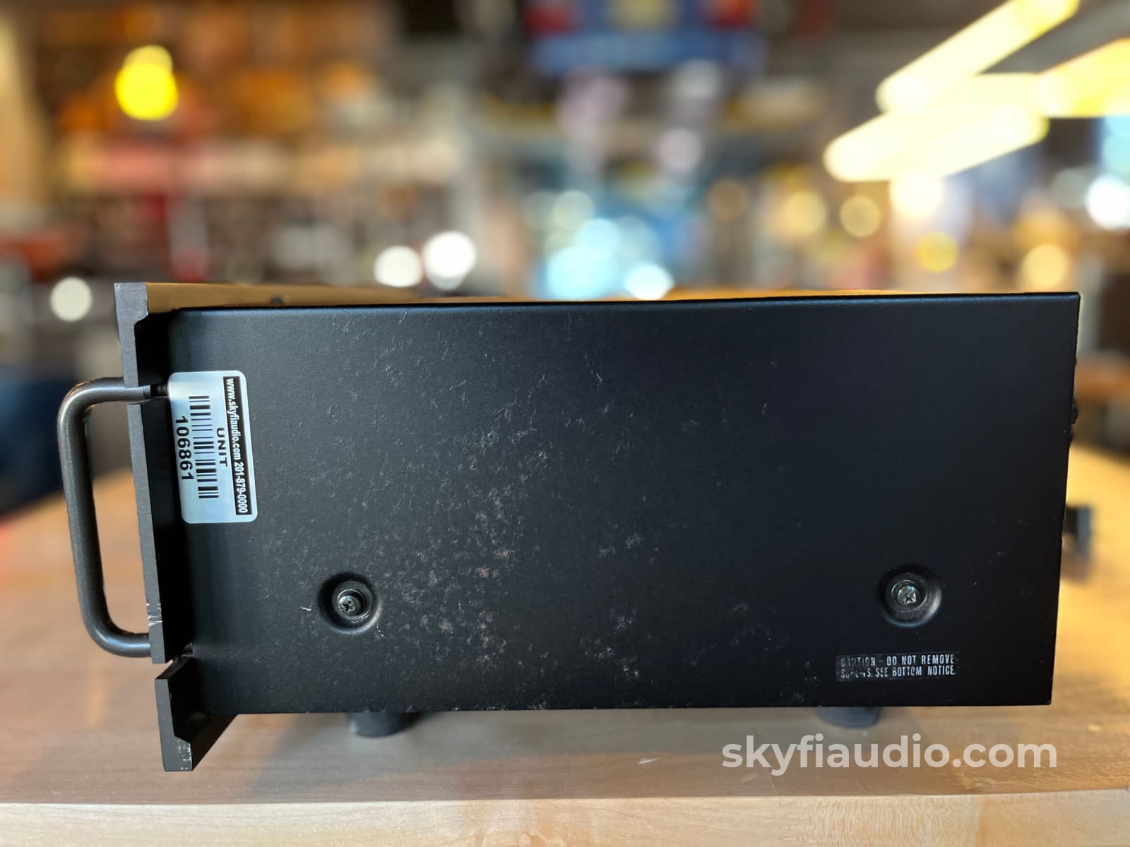
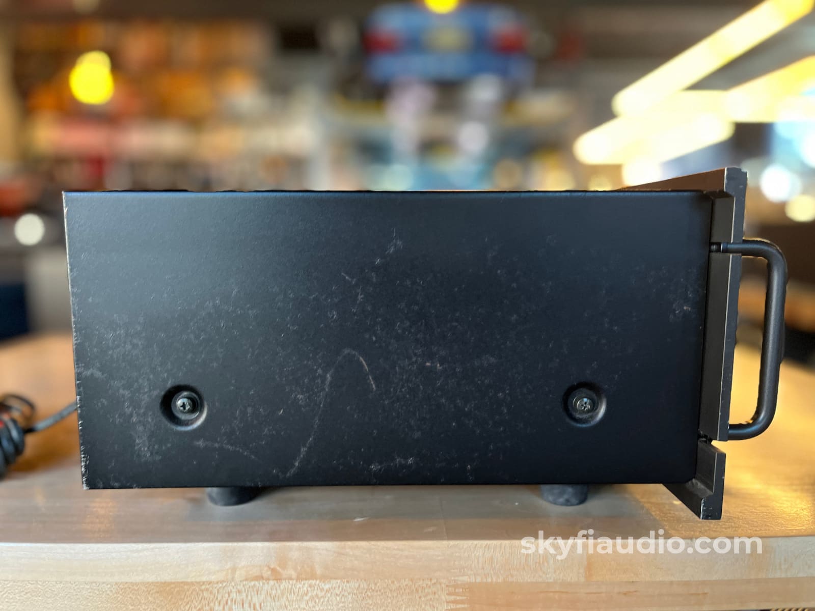
This unit has some marks mostly visible at the sides and top of its case. It also has a few scratches on the edges of the faceplate. Overall it is presentable.
SkyFi Technical Notes:
At some point in the past the power cord's end was replaced. This unit was likely used overseas and had a European style plug and was changed when the unit was brought to the USA. We checked it our on our bench confirmed full power capabilities, cleaned controls, checked all suspect components. Works like a charm.
Brand Background:
At Technics we understand that the listening experience is not purely about technology but the magical and emotional relationship between people and music. We want people to experience music as it was originally intended and enable them to feel the emotional impact that enthuses and delights them. With a combination of our love of music and the vast high-end audio experience of the Technics team, we stand committed to building a brand that provides the ultimate emotive musical experience by music lovers, for music lovers.
Ownership:
Second Owner
Connections:
RCA, Speaker Terminals, Captive Power Cord
General Sound:
Smooth, uncolored, undistorted natural and clean
Cosmetic Condition:
6/10 = Fair. Three to four minor scratches, or one major scratch. See our detailed rating description here.
Working Condition:
Working perfectly and tested in our lab and listening room.
Included:
Just the unit and power cord.
Packing:
Will be packed using our highly developed in-house process and custom packing materials.Specs:
Power output: 73 watts per channel into 8Ω (stereo)
Frequency response: 20Hz to 20kHz
Total harmonic distortion: 0.08%
Damping factor: 50
Input sensitivity: 2mV (MM), 150mV (line)
Signal to noise ratio: 73dB (MM), 92dB (line)
Output: 150mV (line), 1V (Pre out)
Speaker load impedance: 4Ω to 16Ω
Dimensions:
17.72 x 6.81 x 13.86
Weight:
28 lbs.
Approximate Age:
1976
Link to Manual:
Click Here
Recommended Cables:
Kimber Kable - RCA Interconnects - Better
Kimber Kable - RCA Interconnects - Best
Kimber Kable - Phono Interconnects
Kimber Kable - BALANCED XLR Connectors - Better
Kimber Kable - BALANCED XLR Connectors - Best
Kimber Kable - Speaker Cables - Better
Kimber Summit Series Monocle XL Speaker Cables (PAIR) - Best
Kimber Summit Series BiFocal XL Bi-Wire Speaker Cables (PAIR) - Best If Applicable
Kimber Kable - Power Cords - Better
Kimber Kable - Power Cords - Best
Kimber Kable - Coaxial Digital Interconnect
Kimber Kable - Optical Digital Interconnect
Kimber Kable - Digital AES/EBU Interconnect
Kimber Kable - Select Series Reference USB Cable
Testing Process:
*Integrated Process followed by Receiver Process. Delete per listing as needed.*
We start with a visual inspection of all internal components to make sure that there are no signs of heat stress or damage. Capacitors are checked for telltale signs of predictive failure including bulging, shrunken wrappers, or physical leakage. We also inspect the PCBs for discoloration from resistors or transistors that may have been running hot. On vintage units we often spot check select capacitors for value and ESR.
If the device has the ability to decouple the preamplifier from the power amplifier, we remove the jumpers and independently test each section. If the device cannot be decoupled, we assess the electronic condition of the piece by analyzing the speaker level output only.
We start by connecting the "Pre-Out" jacks of the integrated to a Sencore PA81 Power Analyzer which simulates real world loading conditions and gives us an oscilloscope interface. The first order of business is checking that the volume control works smoothly throughout its entire range with acceptable channel balance. This is accomplished by feeding a 1 KHz sine wave into one of the preamp’s line level inputs while monitoring the preamp’s output on an oscilloscope.
We then switch to a 1 KHz square wave to test the tone controls, loudness function, and filters where applicable. During this step we are watching for equal alteration of the test signal by both channels. This also helps us identify dirty controls that will need treatment.
Once the basic line stage functions are verified, we test each input individually. This is especially important for devices that use relays to select their sources.
If the preamp section is equipped with a phono stage we test that as well. We use an inverse RIAA filter which allows us to feed a reference test signal into the phono input with the proper RIAA equalization and level. A square wave or sine sweep is used to verify that the device’s phono stage is faithfully reproducing the RIAA curve.
Next we test the power amplifier section by connecting the integrated amplifier speaker outputs to a Sencore PA81 Power Analyzer which acts as a dummy load, DC offset monitor, and oscilloscope interface. We start with a low level 1 KHz test signal at the "Main In” jacks and slowly increase its amplitude while monitoring the output on an oscilloscope for signs of noise, clipping, distortion, or improper channel balance. We continue increasing the signal level until the amplifier reaches clipping.
At this point we take an output power measurement and compare it to the spec sheet of the amplifier to verify proper performance. We finish off the bench evaluation with a 1 KHz square wave check and a 20 Hz to 20 KHz sine sweep to assess the amplifier’s frequency response characteristics.
This battery of tests will usually reveal if the amplifier has any issues that need further attention.
If the preamp and power amp both pass these tests, we reconnect the sections and verify that the preamp section can drive the power amp to rated power with a 1KHz tone on one of the line level inputs.
Before the device leaves the bench, we perform a listening test with actual music using a variety of preferred test tracks. Our benches are outfitted with familiar monitor speakers which help us identify inconsistencies that will not always show up on our test gear. The main things that we are listening for are hum or noise with no signal present, proper center image, clicks, pops, or any other obvious undesirable audio characteristics.
If the unit passes all of these tests it moves to our long term testing rig where we simulate real word operating conditions for 6-8 hours minimum. This allows us to monitor the unit for signs of thermal runaway or intermittent issues that only crop up when the unit has fully come up to temperature.
We start with a visual inspection of all internal components to make sure that there are no signs of heat stress or damage. Capacitors are checked for telltale signs of predictive failure including bulging, shrunken wrappers, or physical leakage. We also inspect the PCBs for discoloration from resistors or transistors that may have been running hot. On vintage units we often spot check select capacitors for value and ESR.
If the device has the ability to decouple the preamplifier from the power amplifier, we remove the jumpers and independently test each section. If the device cannot be decoupled, we assess the electronic condition of the piece by analyzing the speaker level output only.
We start by connecting the "Pre-Out" jacks of the receiver to a Sencore PA81 Power Analyzer which simulates real world loading conditions and gives us an oscilloscope interface. The first order of business is checking that the volume control works smoothly throughout its entire range with acceptable channel balance. This is accomplished by feeding a 1 KHz sine wave into one of the preamp’s line level inputs while monitoring the preamp’s output on an oscilloscope.
We then switch to a 1 KHz square wave to test the tone controls, loudness function, and filters where applicable. During this step we are watching for equal alteration of the test signal by both channels. This also helps us identify dirty controls that will need treatment.
Once the basic line stage functions are verified, we test each input individually. This is especially important for devices that use relays to select their sources.
If the preamp section is equipped with a phono stage we test that as well. We use an inverse RIAA filter which allows us to feed a reference test signal into the phono input with the proper RIAA equalization and level. A square wave or sine sweep is used to verify that the device’s phono stage is faithfully reproducing the RIAA curve.
To test the tuner, we connect one of the tape outputs to the Sencore PA81 and the antenna terminals to a Sencore SG80 which allows us to “simulate” an ideal radio station using precision test signals instead of music. This device, in conjunction with an oscilloscope allows us to properly evaluate the following parameters:
1) AM Reception (Where Applicable)
2) FM Mono Reception & Tuning Meter Function
3) FM MPX Reception (Stereo)
4) Dial Tracking: How accurately the tuner dial or display indicates the actual frequency of the broadcast being received.
5) Stereo Separation: A properly working stereo tuner will have minimal crosstalk between the left and right channel.
6) Sensitivity & Signal Strength Meter Function: By lowering the output of the SG80 we can simulate weak stations and determine how well the tuner will be able to pull in weak distant stations. This adjustment also helps us verify signal strength meter function.
If the tuner has acceptable performance related to the parameters above, we connect the unit for listening tests with a simple dipole antenna. We listen for audio reproduction quality of local stations and evaluate how many stations the tuner can receive while we sweep through the dial. We are looking to verify that the tuner can decode stereo on strong local broadcasts and pick up a wide variety of local stations at the bottom, middle, and top of the frequency band. At this point we also test convenience features such as muting, filters, built in oscilloscope function, etc.
Next we test the power amplifier section by connecting the receiver's speaker outputs to a Sencore PA81 Power Analyzer which acts as a dummy load, DC offset monitor, and oscilloscope interface. We start with a low level 1 KHz test signal at the Main In” jacks and slowly increase its amplitude while monitoring the output on an oscilloscope for signs of noise, clipping, distortion, or improper channel balance. We continue increasing the signal level until the amplifier reaches clipping.
At this point we take an output power measurement and compare it to the spec sheet of the amplifier to verify proper performance. We finish off the bench evaluation with a 1 KHz square wave check and a 20 Hz to 20 KHz sine sweep to assess the amplifier’s frequency response characteristics. This battery of tests will usually reveal if the amplifier has any issues that need further attention.
If the preamp and power amp both pass these tests, we reconnect the sections and verify that the preamp section can drive the power amp to rated power with a 1 KHz tone on one of the line level inputs.
Before the device leaves the bench, we perform a listening test with actual music using a variety of preferred test tracks. Our benches are outfitted with familiar monitor speakers which help us identify inconsistencies that will not always show up on our test gear. The main things that we are listening for are hum or noise with no signal present, proper center image, clicks, pops, or any other obvious undesirable audio characteristics.
If the unit passes all of these tests it is moved to our long term testing rig where we simulate real word operating conditions for 6-8 hours minimum. This allows us to monitor the unit for signs of thermal runaway or intermittent issues that only crop up when the unit has fully come up to temperature.
Choose options