Bang & Olufsen Beogram 6500 Complete System
Free Shipping on Most Electronics - Excludes Speakers and Items Requiring Freight - Contiguous U.S. Only
Pickup currently unavailable at SkyFi 479

Bang & Olufsen Beogram 6500 Complete System
SkyFi 479
479 South Broad Street
Glen Rock NJ 07452
United States
General:
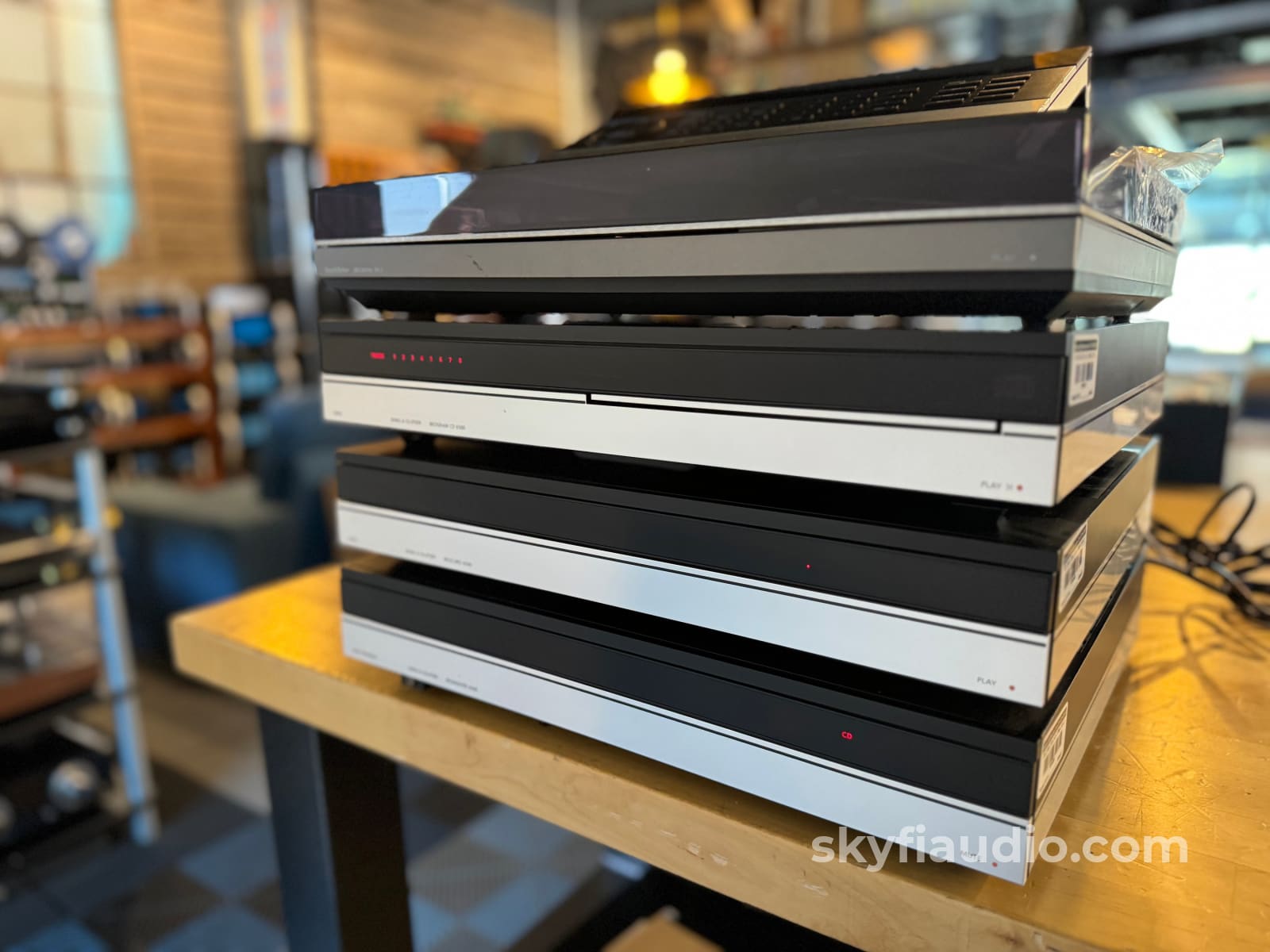
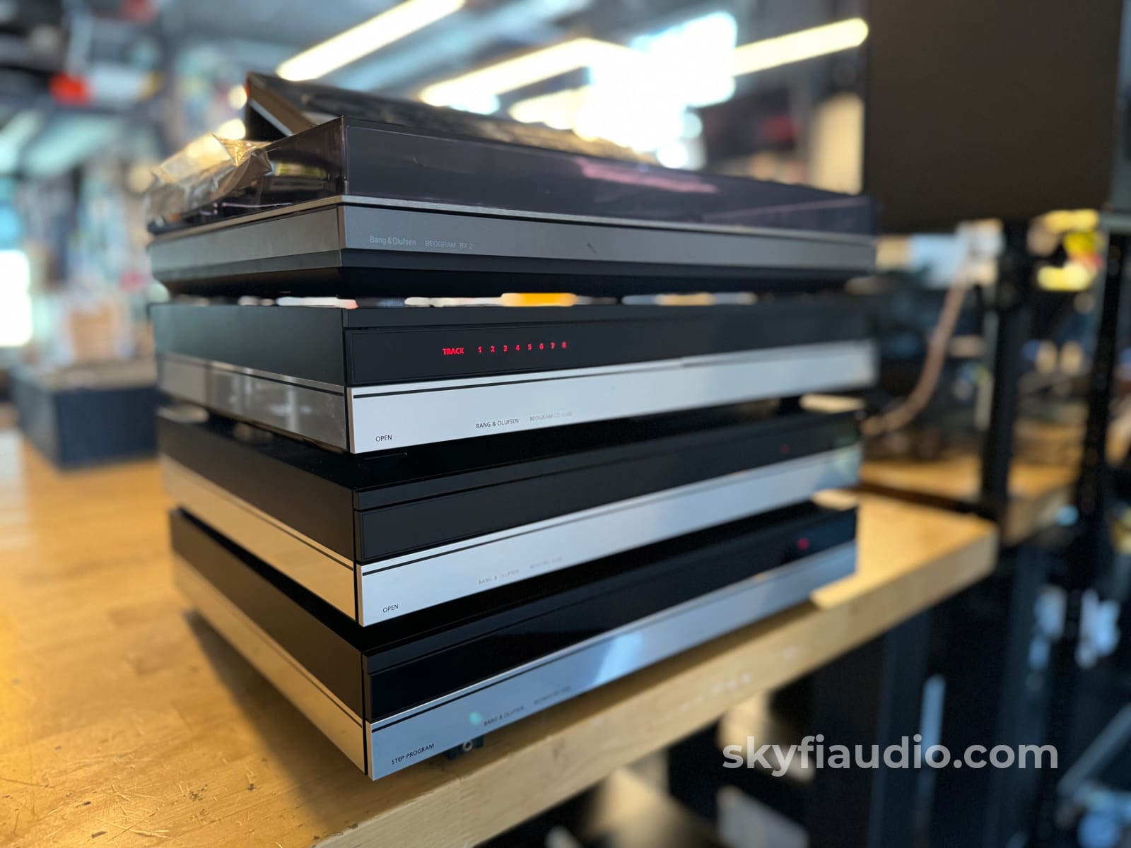
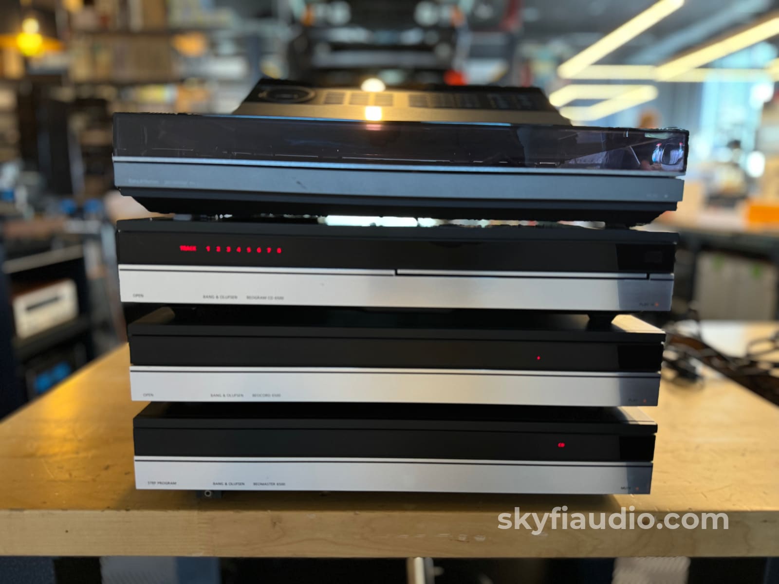
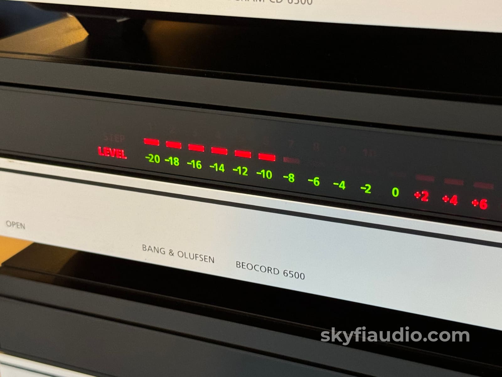
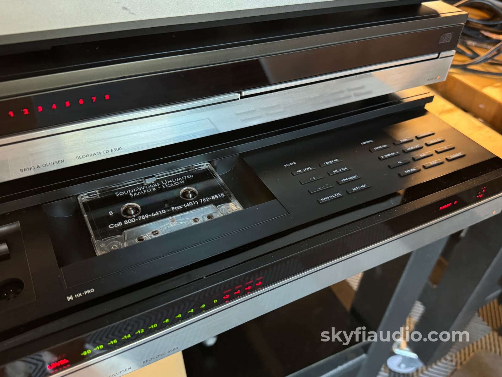
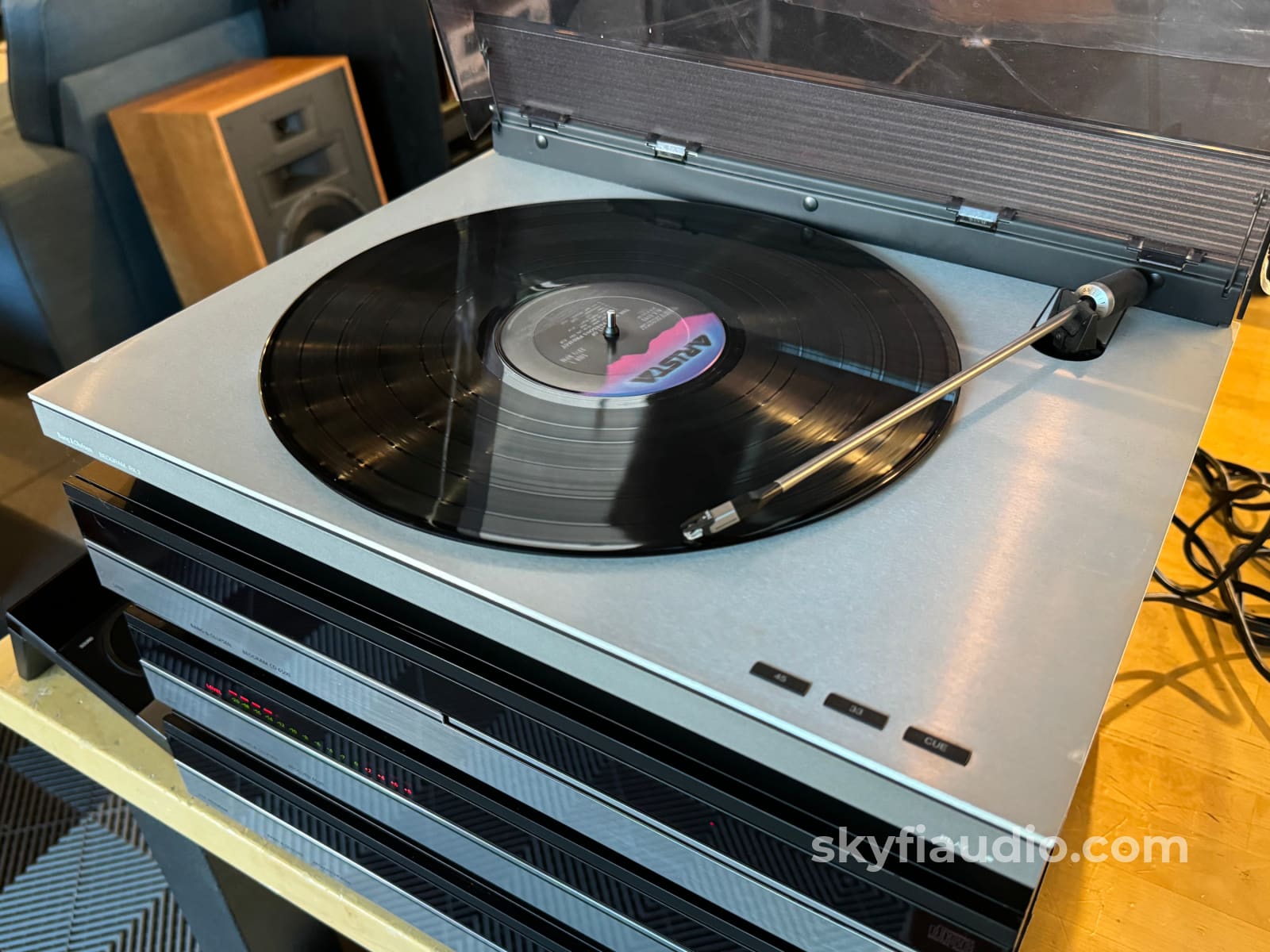
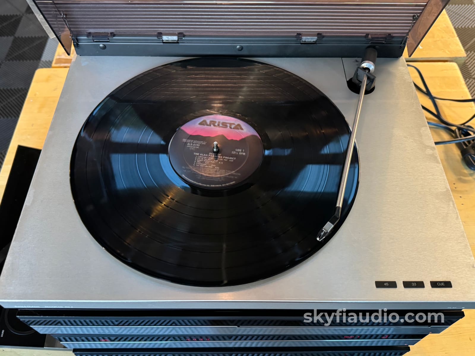
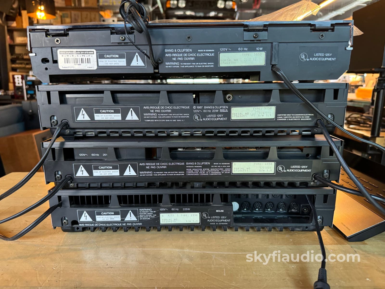
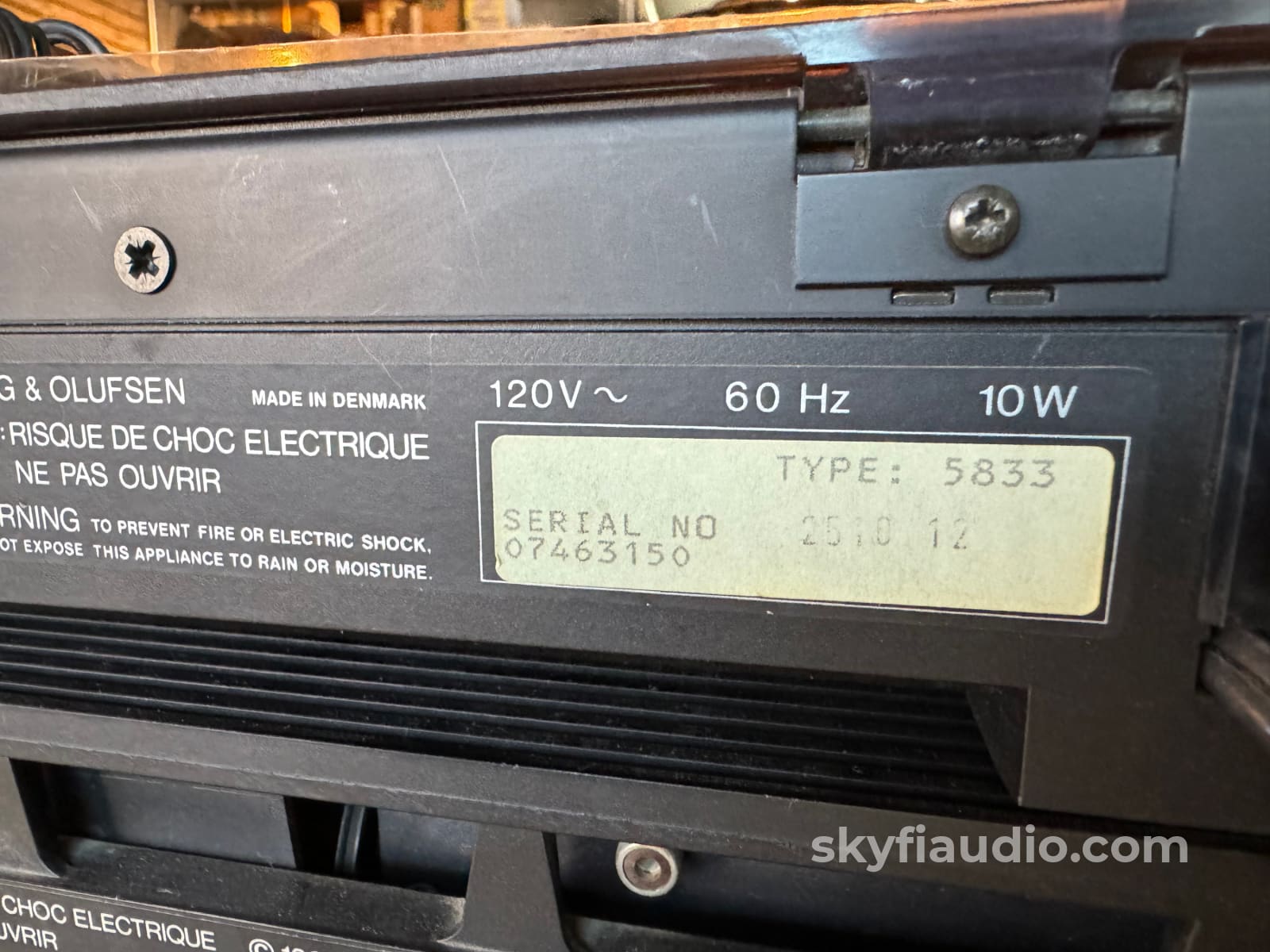
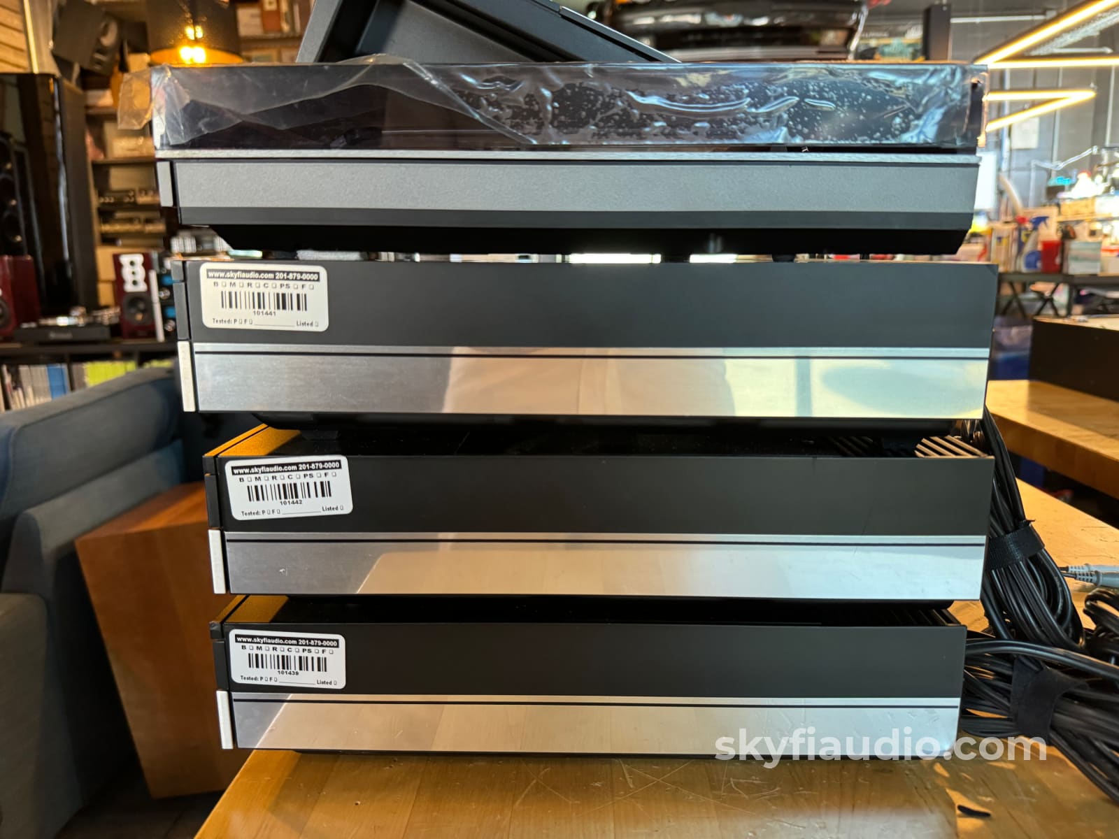
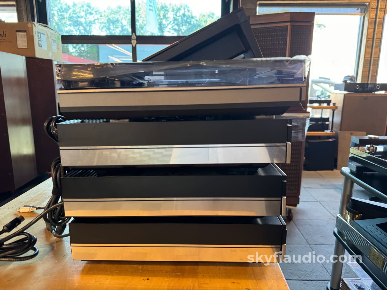
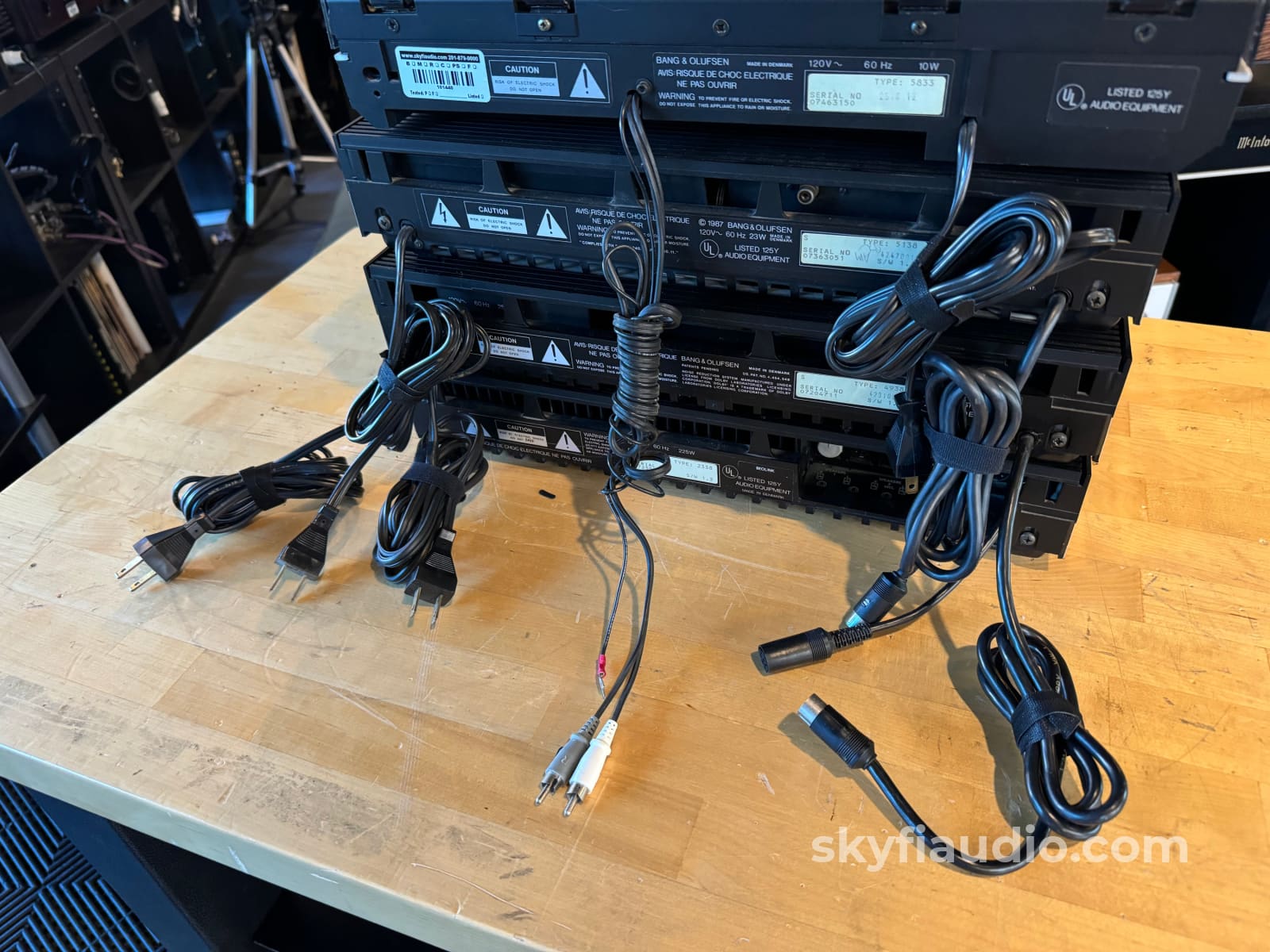
This is a rare and complete Bang & Olufsen HiFi setup straight from late 1980's and early 1990's. It includes a CD Player, Receiver, Cassette Deck, Turntable, Remote and connecting cables.
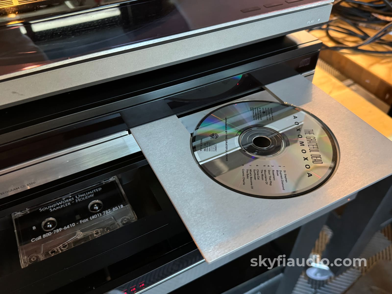
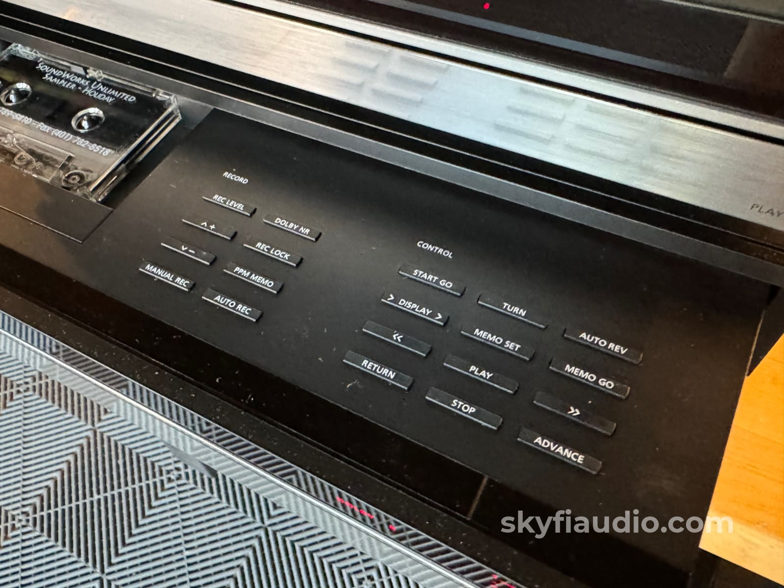
It has an amazing design, especially when the components are separated horizontally. Plus it features a super cool power loading drawer cassette deck.
This set is working well and is a perfect addition for any B&O collector.
All components were lightly serviced, received new belts (where applicable), and underwent a thorough cleaning and lubrication.
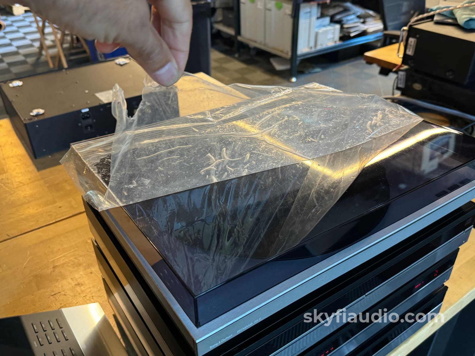
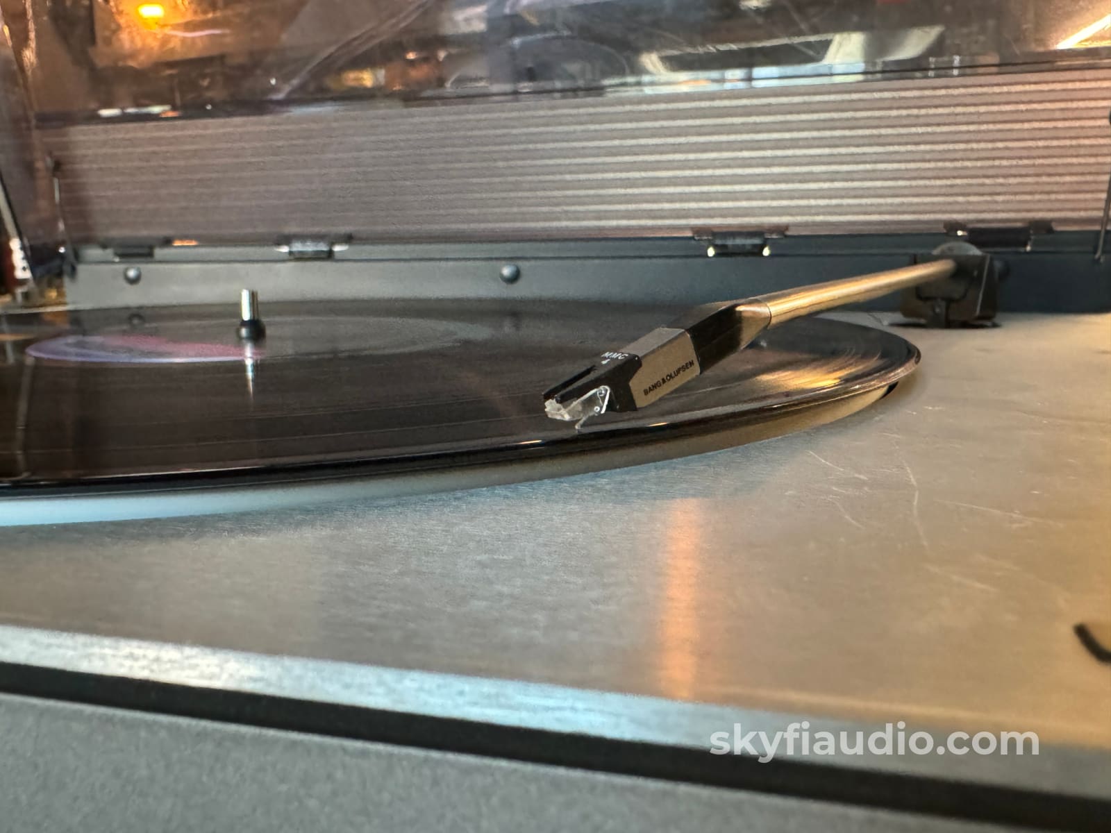
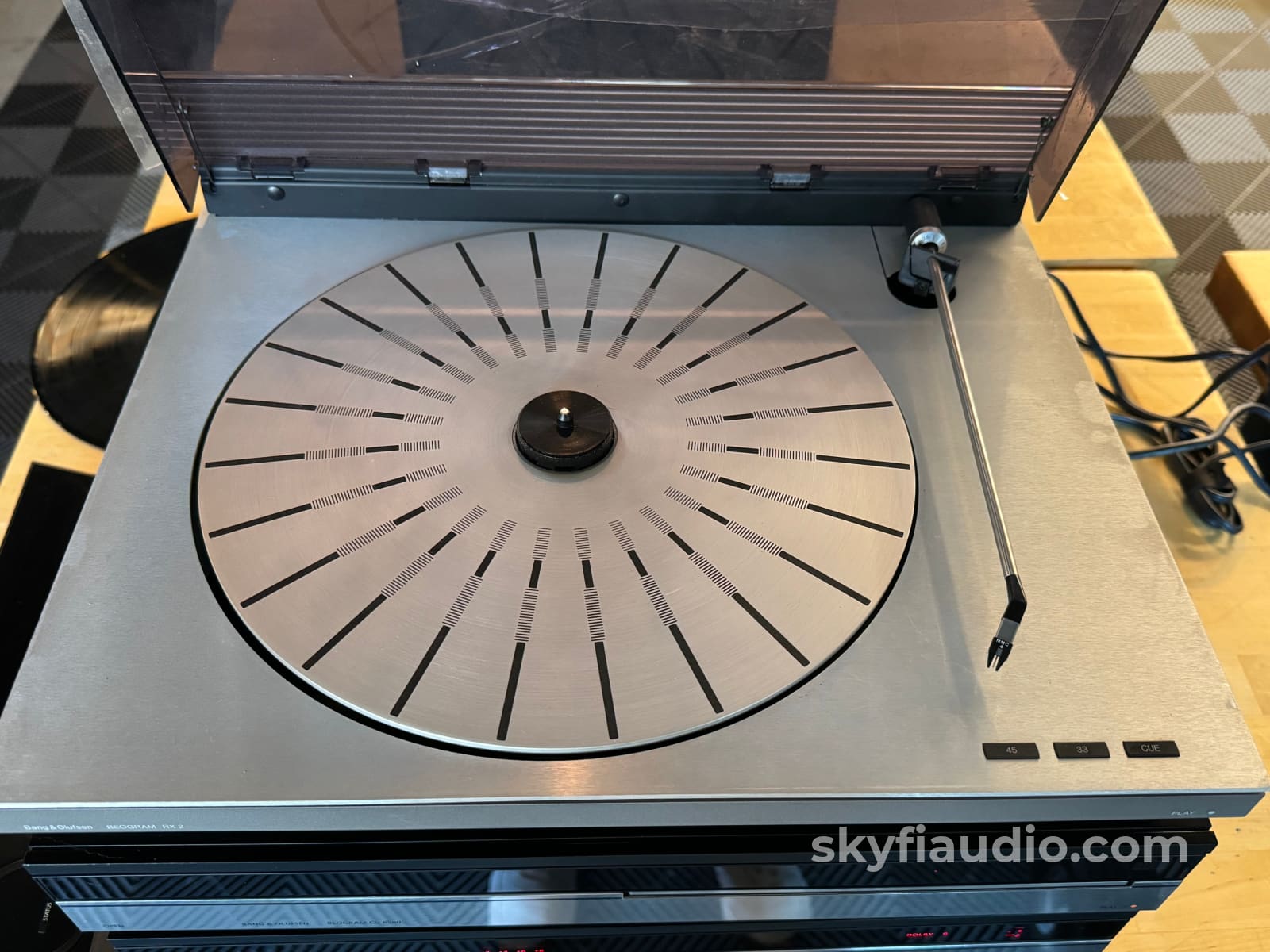
The turntable looks like it was never used and actually still has the protective plastic on the cover. The cartridge is a superb MMC4 showing no signs of use after careful inspection under our shop microscope.
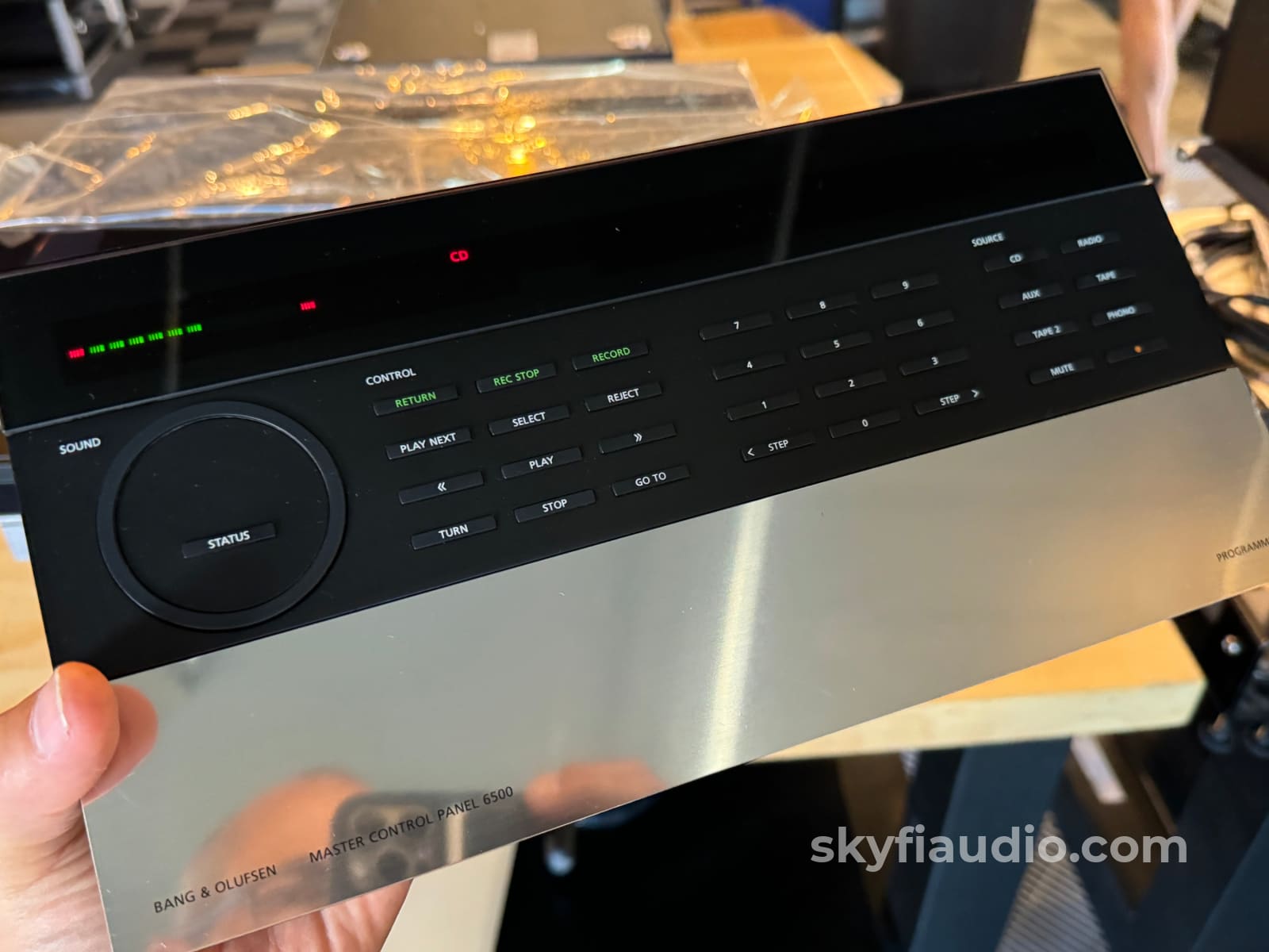
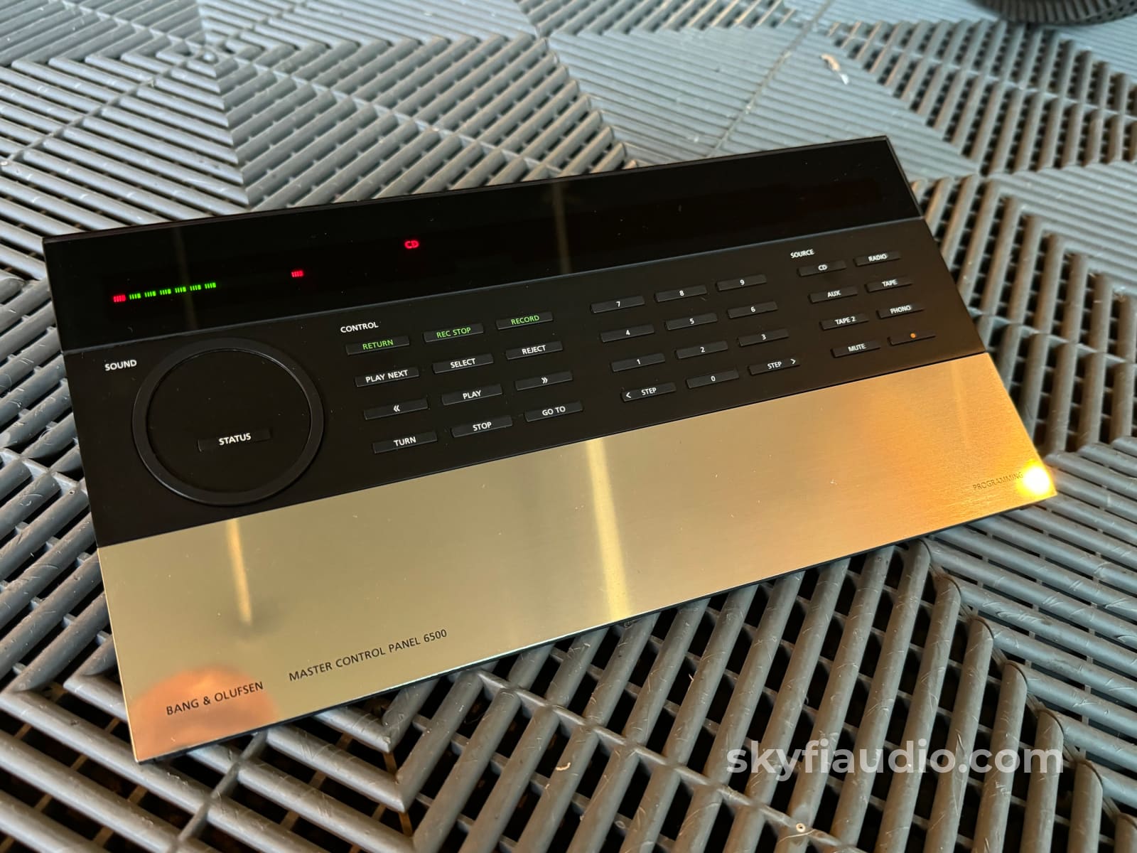
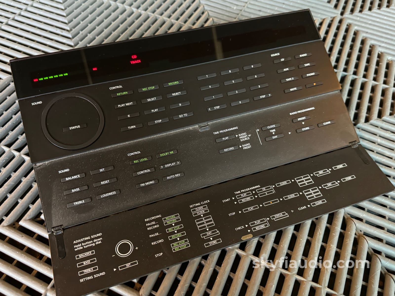
The Master Control Remote is super interesting with 2-way feedback for volume and time, along with a large well-lit display. There are buttons for just about everything!
This listing includes:
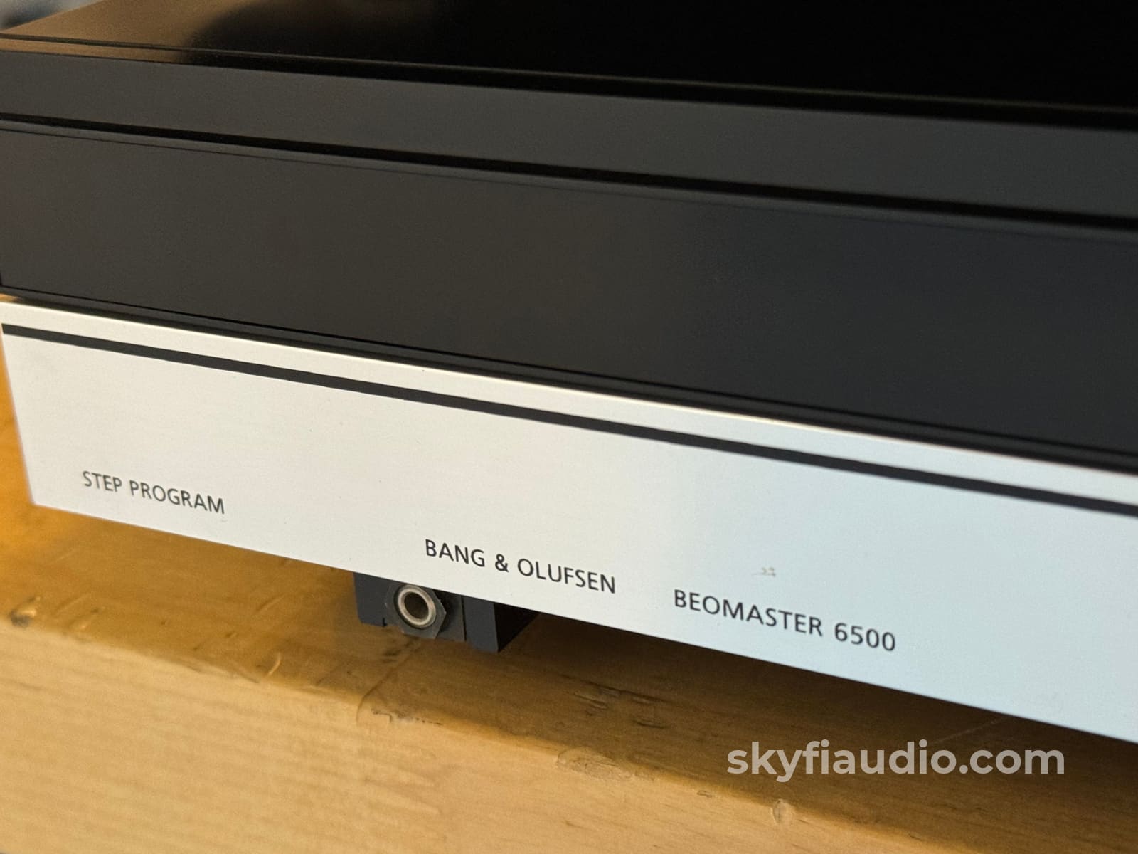
• Beomaster 6500 (Receiver)
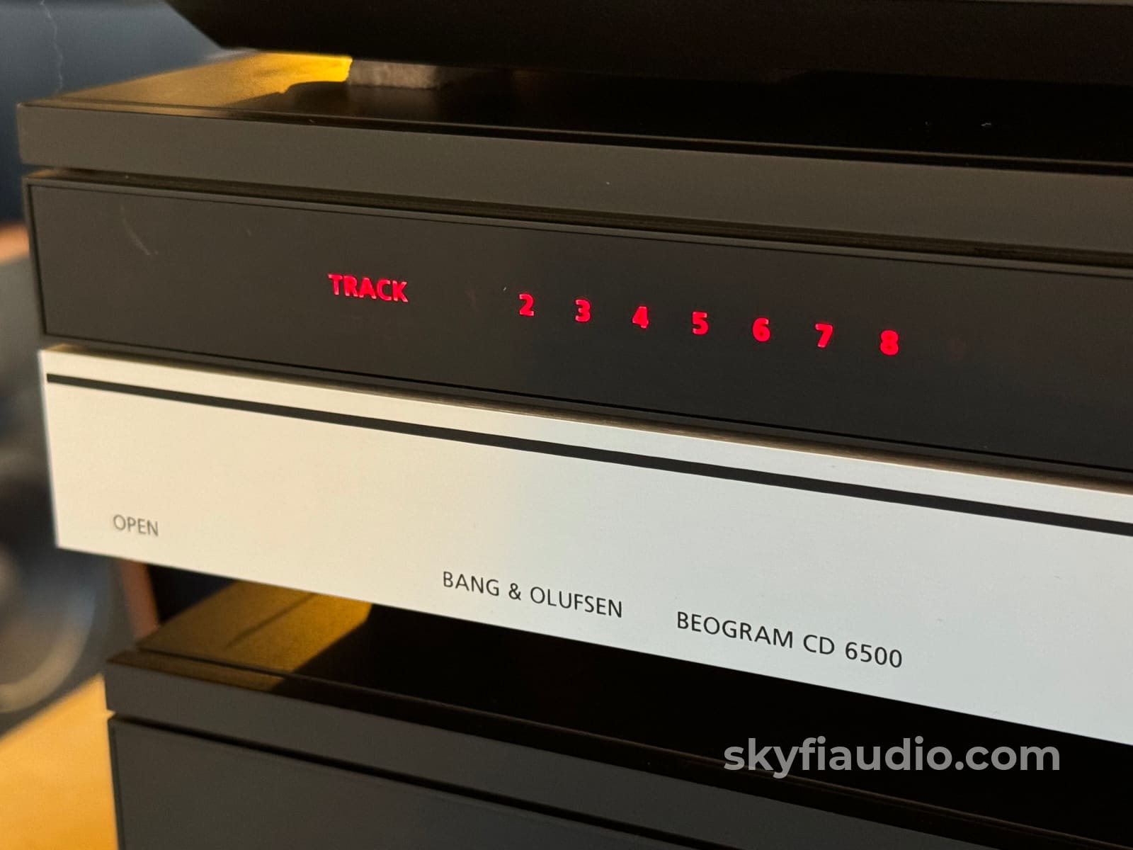
• Beogram CD 6500 (CD Player)
• Beocord 6500 (Cassette Deck)
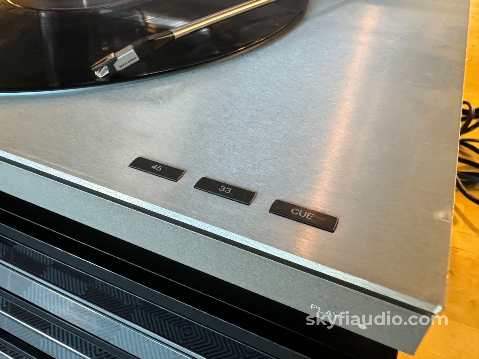
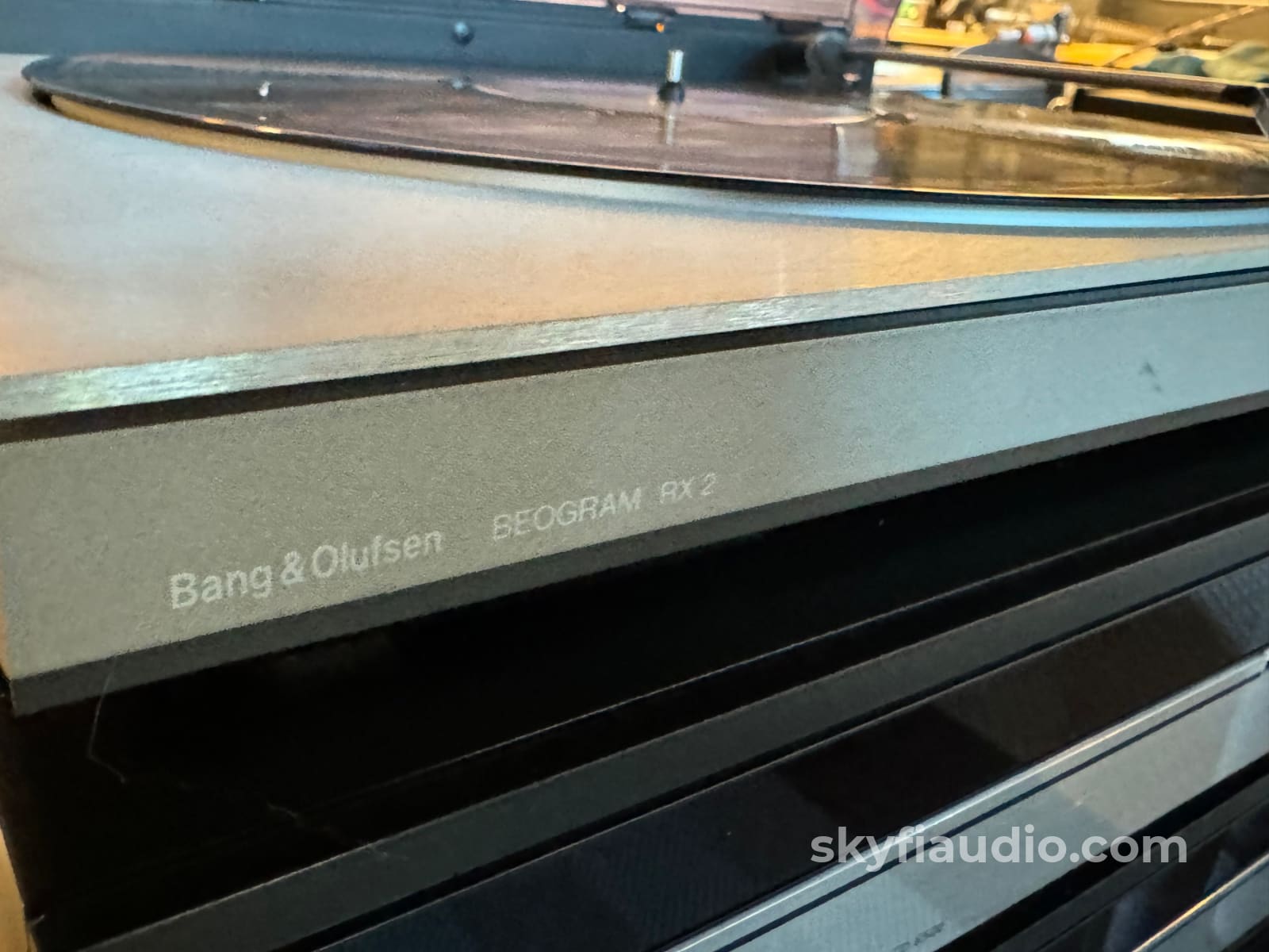
• Beogram RX-2 (Turntable)
• Master Control Panel 6500 (Remote)
SkyFi Cosmetic Notes:
The components have some marks on the front panels and some surface scratches. Presentable condition overall.
Brand Background:
Bang & Olufsen (B&O) is a Danish high-end consumer electronics company that designs and manufactures audio products, television sets, and telephones. It was founded in 1925 by Peter Bang and Svend Olufsen, who designed a radio to work with alternating current, a product of significance at a time when most radios were still running on batteries.
Ownership:
Single Owner
Connections:
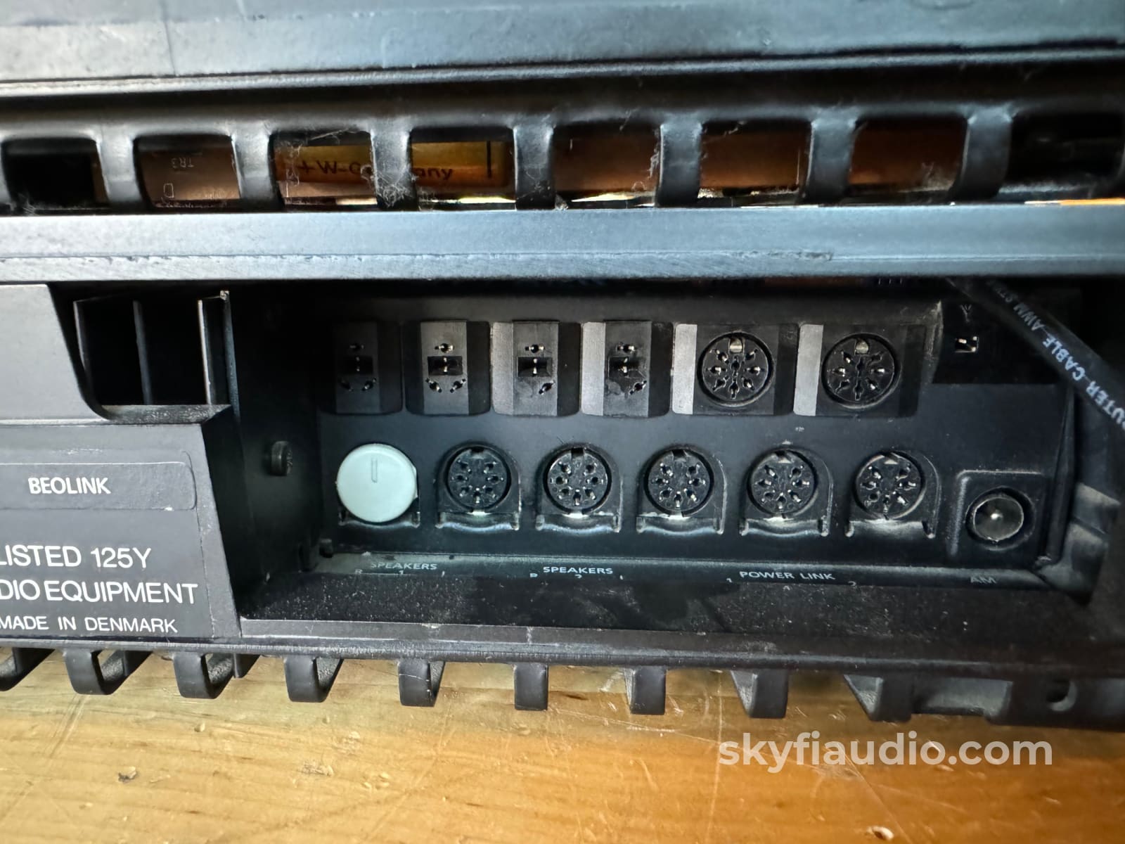
B&O style DIN connectors
General Sound:
Smooth, uncolored, undistorted natural and clean
Cosmetic Condition:
6/10 = Fair. Three to four minor scratches, or one major scratch. See our detailed rating description here.
Working Condition:
Working perfectly and tested on our bench with both CD and DVD. XLR and RCA working as they should.
Included:
Exactly as pictured and described above.
Packing:
Will be packed using our highly developed in-house process and custom packing materials.Weight:
60 lbs.
Approximate Age:
1989
Testing Process - Tape Decks:
First steps are performed to determine if the unit is a candidate for our full restoration process, or if it's just in need of a light service.
We perform a basic functionality test to ensure proper playback, fast forward, and rewind. We look for smooth operation of the motors, transport engagement, and associated rolling parts.
We then do an internal physical inspection to ensure the belts and rubber consumable parts are up to spec.
Internal components are checked to make sure there are no signs of heat stress or damage, particularly in the power supply section. Capacitors are checked for telltale signs of predictive failure including bulging, shrunken wrappers, or physical leakage. We also inspect the PCBs for discoloration from resistors or transistors that may have been running hot. On vintage units we often spot check select capacitors for value and ESR.
A light service will involve replacement of belts and rollers, external cleaning of heads, mechanism and boards, and basic record and playback tests.
A full restoration will often include disassembly of the drive system and replacement of all consumable and wearable parts including pinch rollers, belts, brakes, and bearings. We then clean, lubricate, and re-assemble the drive and perform basic mechanical alignment to ensure proper tape path and head alignment.
Final calibration will involve adjustment of the playback, erase, and record heads, along with optimization of the bias for a specific tape type. We do this with the aid of a Sound Technology 1510A tape deck analyzer plus a Nakamichi T-100 Audio Analyzer with reference calibration tapes.
Final listening tests are performed while monitoring with our reference Grado HP-1 headphones and a variety of factory and custom reference recordings We find that there is no better system for critical listening on tapes than with headphones, especially when comparing a live feed to a recorded feed.
Testing Process - CD Players:
We start with a visual inspection of all internal components to make sure that there are no signs of heat stress or damage. Capacitors are checked for telltale signs of predictive failure including bulging, shrunken wrappers, or physical leakage. We also inspect resistors and other passive components for signs of overheating. When the unit is first powered on we check the drawer mechanism function.
After the visual inspection we connect the CD Player RCA outputs to our Sencore PA81 Power Analyzer which simulates a real world input impedance and allows us to monitor the output on an oscilloscope. We start with a test CD with precision test signals to verify proper output on both channels. If the CD player has balanced outputs these are also tested at this time.
If this check passes, we move onto evaluation with actual music CDs. We listen for clicks, skips, and drops during playback. At this time we also check the transport functions including Play, Pause, Stop, Repeat Track, Next Track, Previous Track, Fast Forward, Rewind, and programming if applicable. If the unit has a remote control, all remote control functions are verified.
If the CD player is capable of SACD playback we test its ability to read SACD layers on multiple discs including standard and hybrid SACD's. At this time we also check the unit’s digital outputs where applicable. If SACD layers are being properly read we should see the digital outputs mute during playback. On redbook CD playback we verify that each digital output maintains proper lock on our bench DAC.
After bench testing is completed, CD players are set up for testing on our long term test rig. During extended testing we make sure that unit can play through several different discs from beginning to end with no skips or lockups.
Testing Process - Turntables:
First we try to identify any mechanical issues, particularly in the tonearm bearings. We check for freedom of movement or any resistance on both the horizontal and vertical range. There is a quick test for this which involves placing the table on its front edge and allowing the arm to swing freely like a pendulum. We then make any adjustments necessary to achieve minimal resistance and sometimes adjust the bearing pressure. On gimbal tonearms we inspect the cone tip with a magnifier.
We then assess the platter speed using one of several methods, the most accurate being playing a test tone on a test record and measuring the frequency output with a frequency counter or oscilloscope. We also utilize test equipment to measure the wow and flutter to ensure it is within spec. We do this for all speeds available for that particular model (33 RPM, 45 RPM, 78 RPM).
Adjustments are then made to achieve proper speed which will vary depending on the turntable's drive design. Some require an adjustment of an internal or external potentiometer, some will require a pulley or motor adjustment. We also inspect the platter bearing to ensure it is properly lubricated, keeping in mind that some bearings don't require lubrication at all
We then inspect the power supply and address any issues with overworked capacitors, particularly on Linn and later Thorens machines which tend to need attention.
On fully mechanical vintage tables like the Thorens TD-124 and Garrard 301/401 we will go thought the entire mechanism. Then replace any worn parts and lubricate all components necessary to ensure smooth operation, speed change, and low mechanical noise.
When fitting a new phono cartridge we will go through our detailed calibration process which can involve as many as 12 steps depending on the tonearm design. We perform this work on our custom turntable calibration rig which was developed in-house.
Some of these steps include:
• Pivot to Spindle Adjustment
• Tracing Force
• Anti-Skate
• Tonearm Height
• Lifter Height
• VTA (Vertical Tracking Angle)
• Azimuth
• Stylus Distance and Overhang
We then do a critical listening test using our test records and our test system to ensure proper sonics.
The SkyFi Testing Process for Cables:
Cables are generally pretty simple and do not require a great deal of testing. We do, however, perform a visual inspection of all of the connectors for damage or significant wear. Most power and interconnect cables can be verified with a simple continuity test with a digital multimeter. Some cables feature dielectric bias systems which are powered by external power supplies or batteries. These devices are checked for proper function where applicable.
We do not perform A/B comparisons of cables in real world conditions and cannot offer objective observations in this regard.
Choose options


